Practicing, mixing tracks and listening to music until it rattles — whenever I like. Traveling through half the city to the rehearsal room to spare the nerves of my roommates is no longer the preferred option. To indulge in self-made noise to your heart's content would be a thing. At this stage someone usually raises the question about headphones: "Yes, no but …" I need a soundproof cabin. PERIOD.
Egg carton and carpets are not enough. A room-in-room construction that largely keeps my sound events away from the outside world should increase my quality of life.
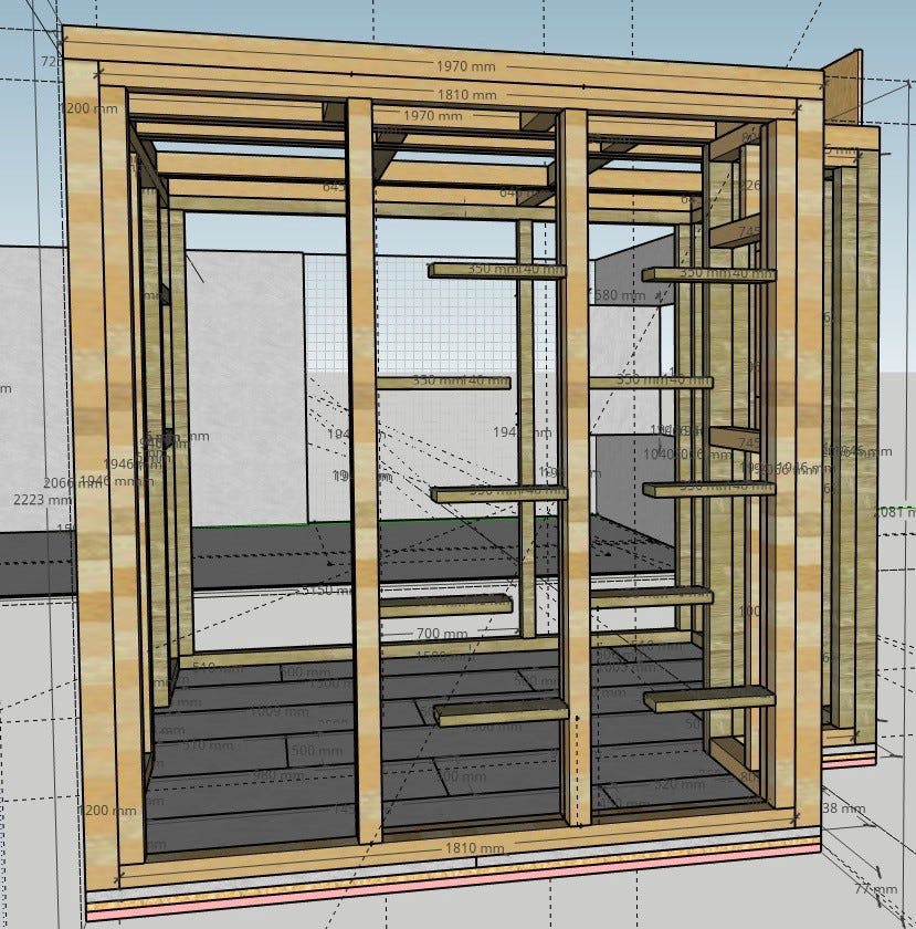
After thinking probably 100 times back and forth whether I should buy a finished product, build it myself, or let it go and continue to complain, I decided to do it myself. Problem: My craft experience is close to zero. Various online forums gave me courage and inspiration. Virtual walking tests with the help of SketchUp gave me first impressions of the construction and materials — as well as quantity and weight.
The Room.
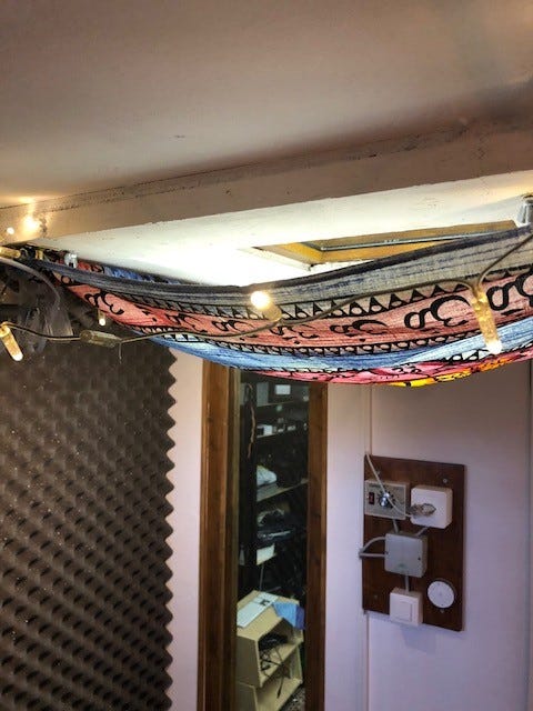
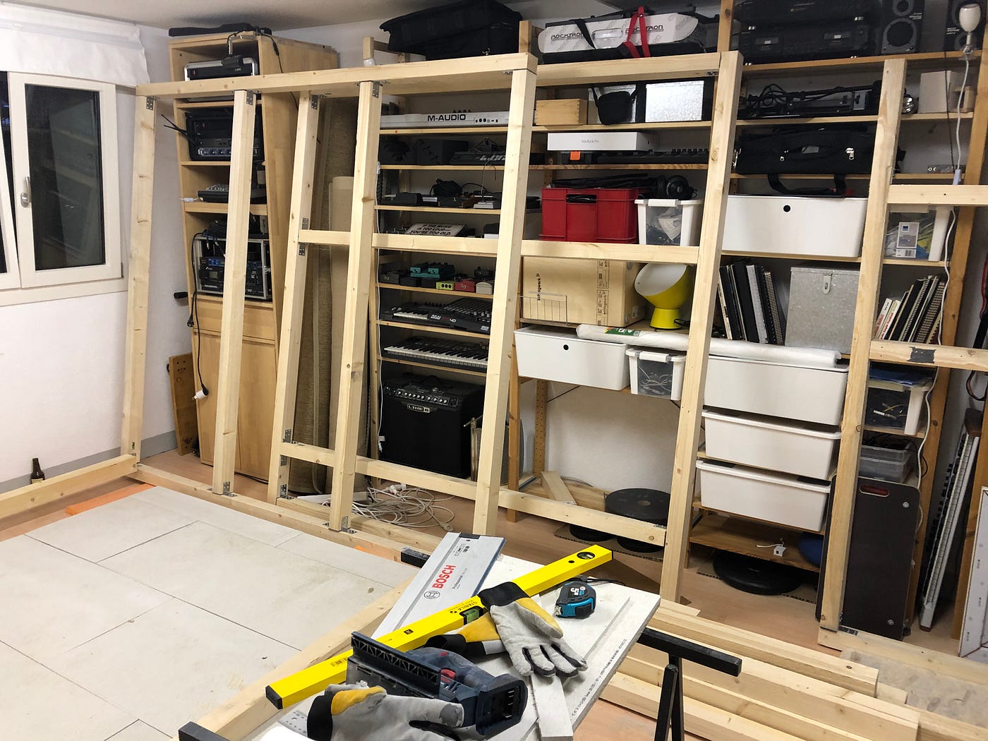
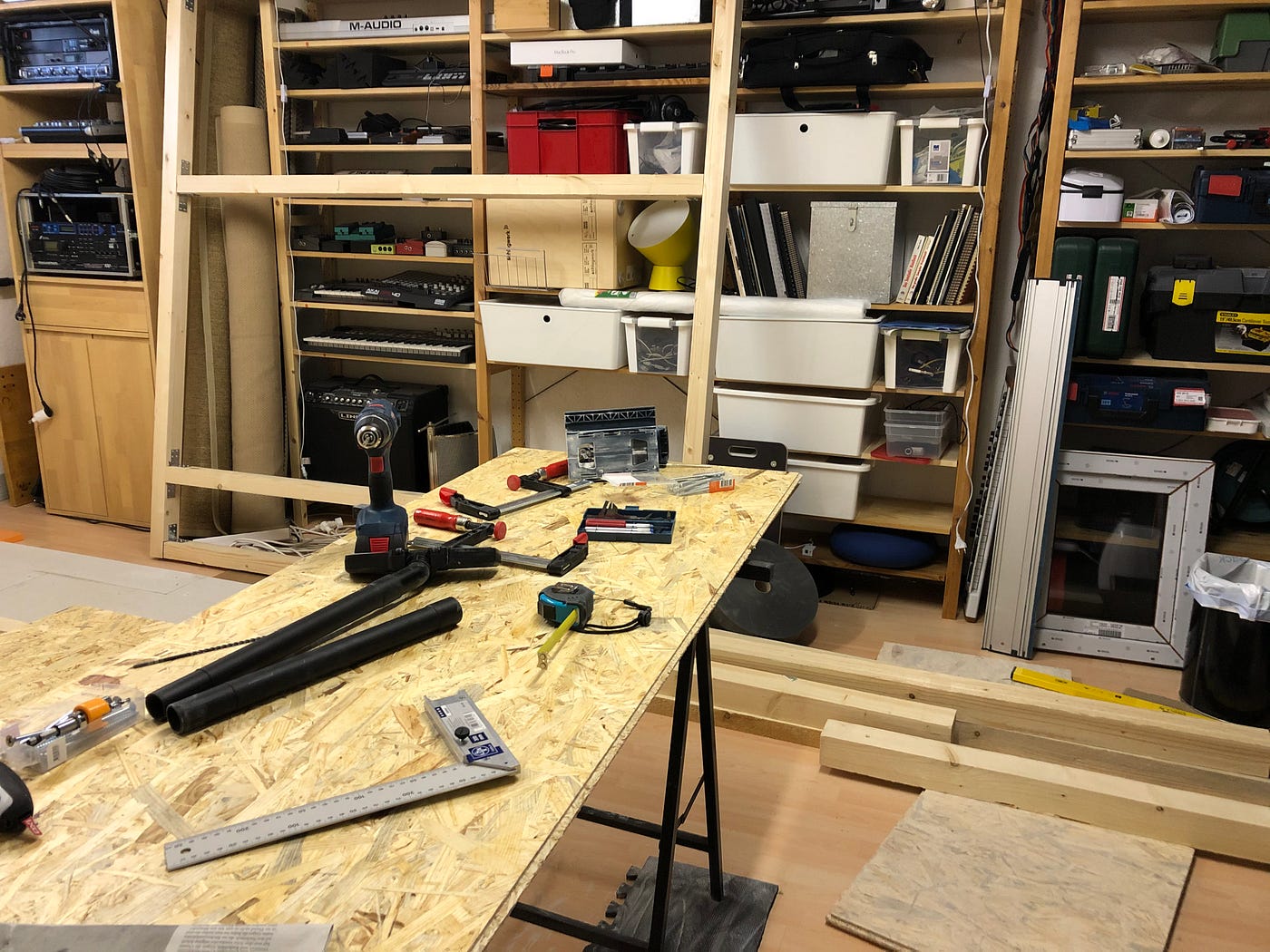
In addition to my apartment, I have rented a craft room that is supposed to serve me as a studio. However, I never feel completely free in it. The concern that my fellow human beings potentially listen to my strumming reluctantly influences my playing. The room currently houses various devices, guitars, cables, stands, etc., and serves more as a warehouse. That should change.
Since the room is rented, I don't want to make any structural changes. I also have to consider the weight of the construction, since the room is not on the lowest level of the house. Common building standards are around 1.5–2 kN/m² (roughly 150–200 kg/m²).
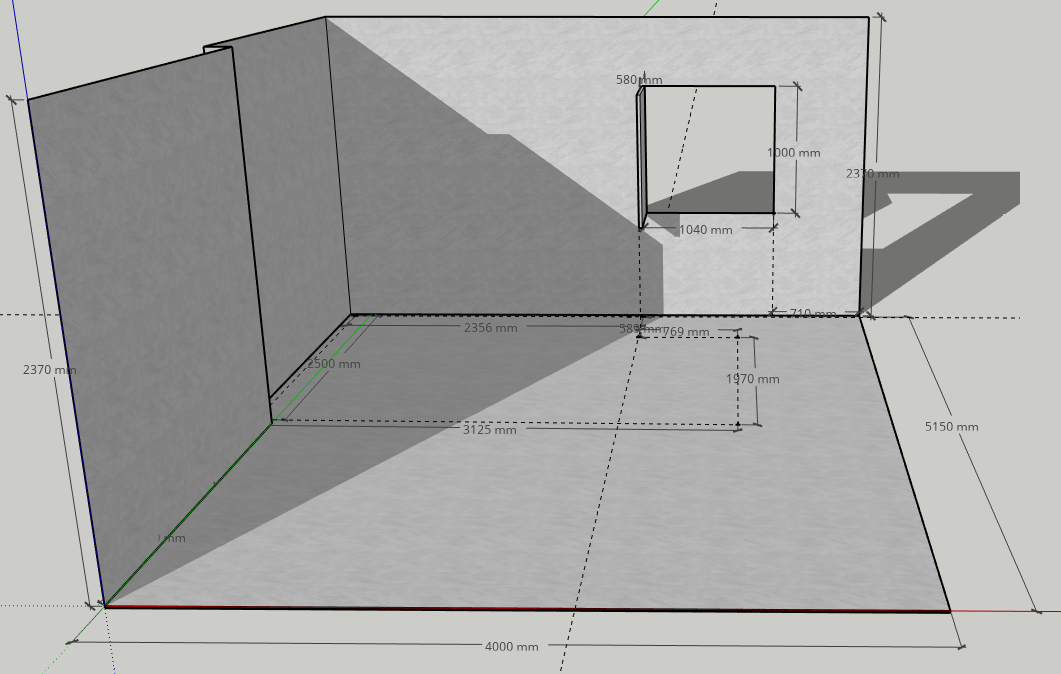
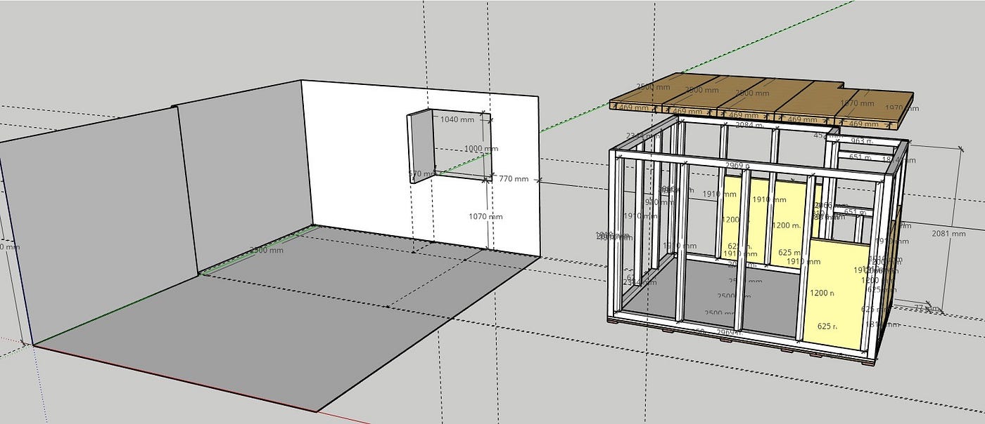
The dimensions of the floor space result from a compromise between requirements, weight, difficulty of construction and conditions of the room. After all, I have about 7.5m² (external dimensions) to make noise. The knowledgeable observer will not overlook the fact that I ignore the no-parallel-sidewall principle — optimal room acoustics is not priority 1. I preferred a simpler construction and will measure and treat the room acoustically later.
The Floor.
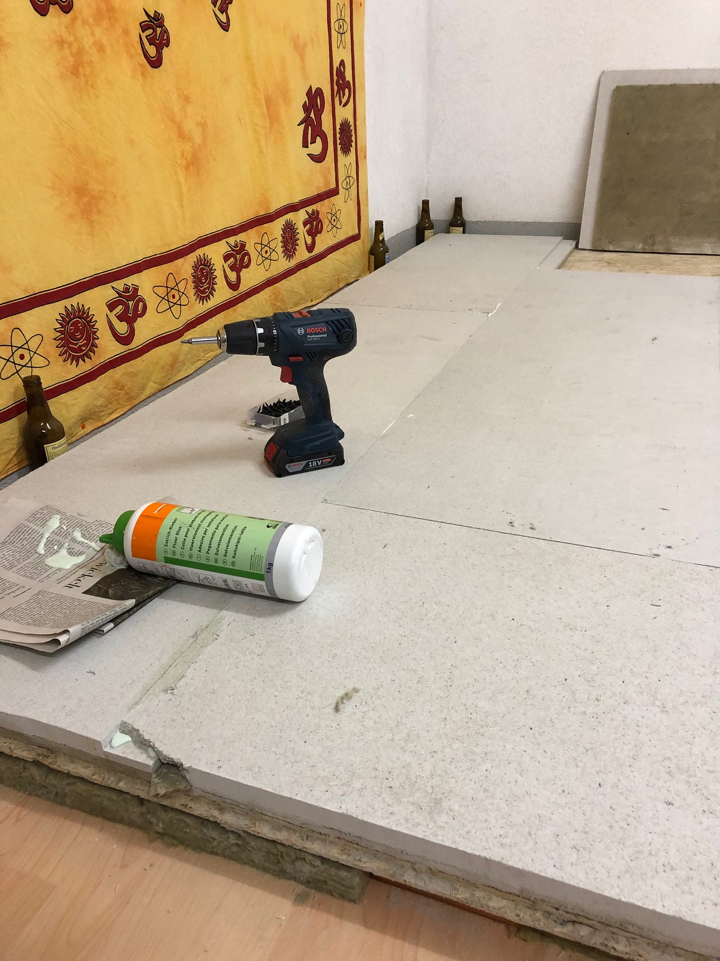
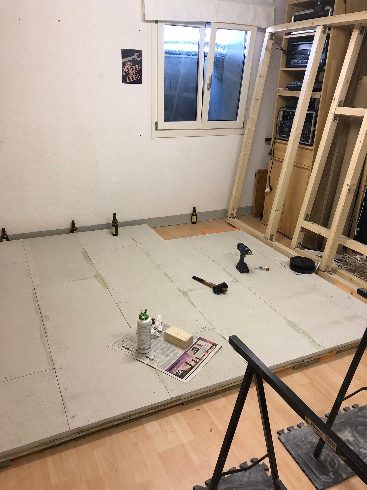
The floor of the cabin is constructed in three layers.
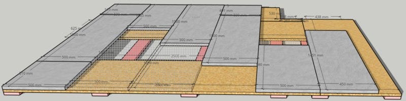
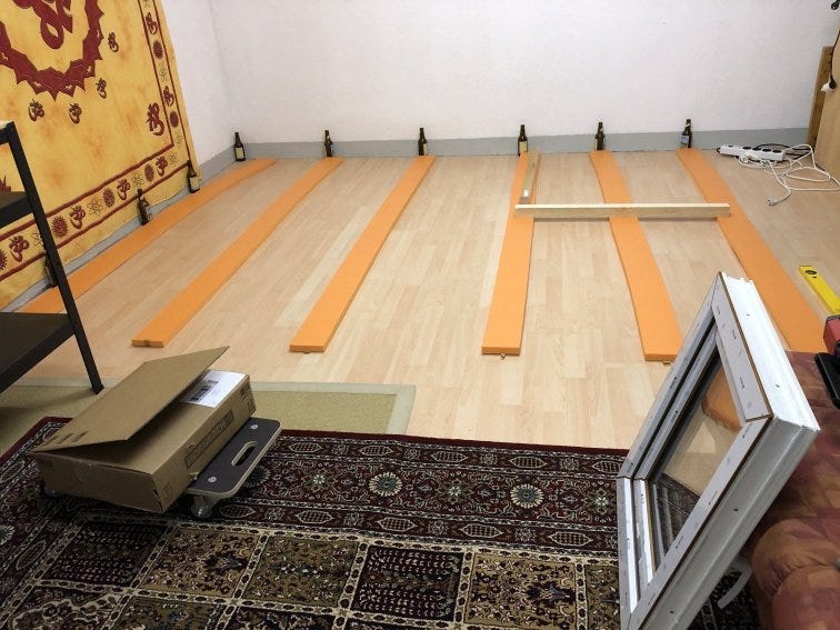
The bottom layer consists of 6 strips of polyurethane plastic — Sylomer (2500mm × 25mm × 125mm). It serves to decouple the construction from vibration. The sound cabin "floats" on this rubber mounting and uses a mass-spring system, as used in railway technology, to prevent sound events in the cabin from resonating in the rest of the world. The rubber strips are the only points of contact between the cabin and the outside world.
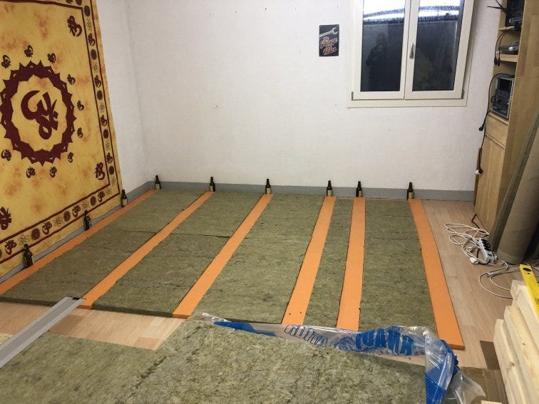
Sylomer is produced in different variants as required with regard to damping and load. I use the standard strips: Sylomer SR 18, 0.018 N/mm², 25mm. 0.018 N/mm² corresponds to approximately 1800 kg/m² — should be enough. I filled the space between the Sylomer strips with 40mm mineral wool. The weight of the upper layers compresses the wool so that the cabin lies on the rubber strip at the end.
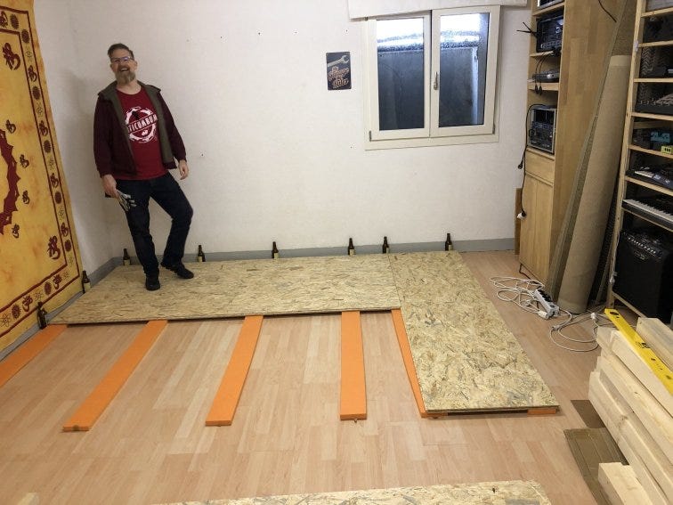
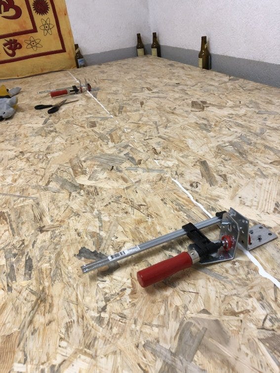
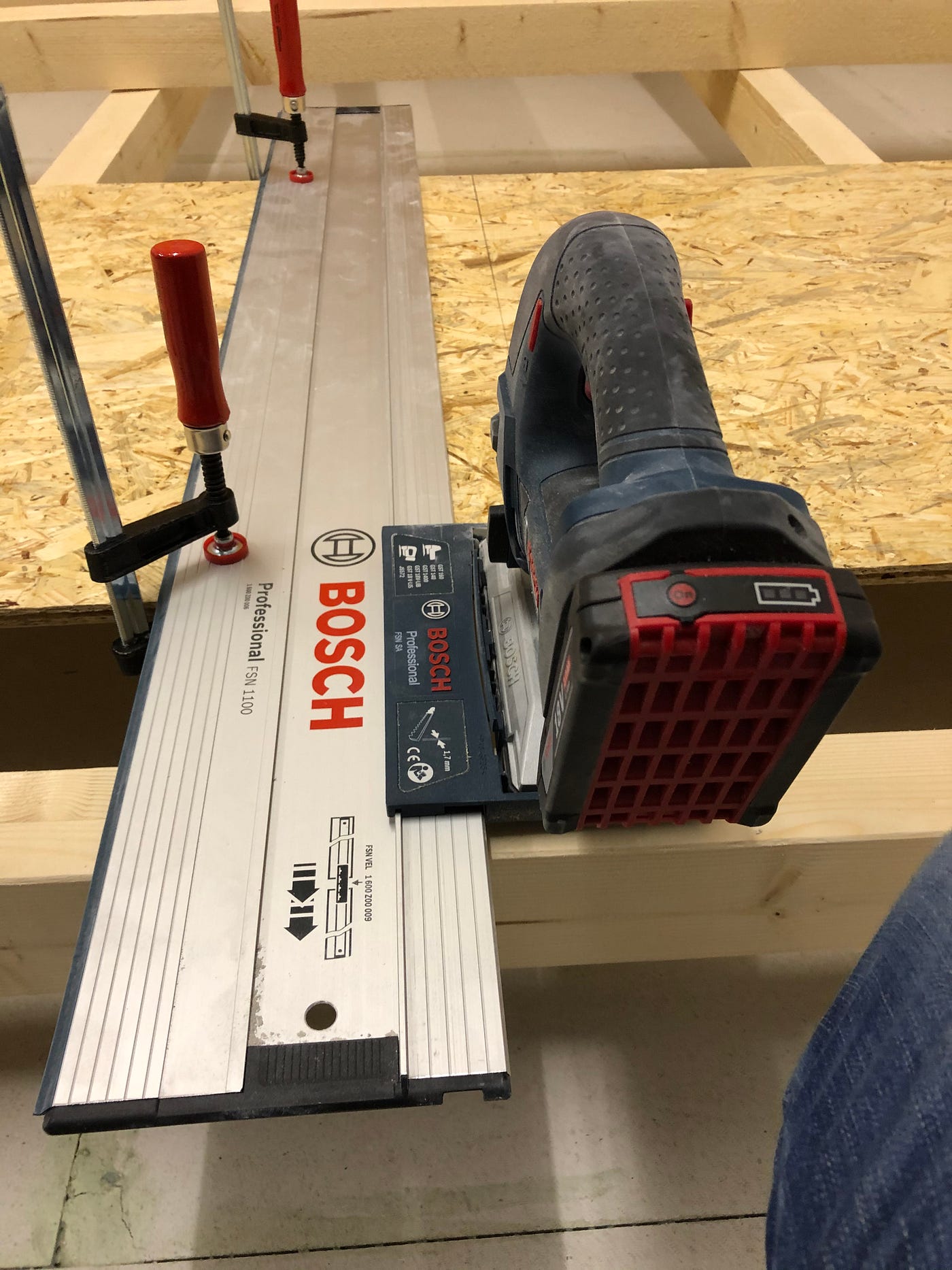
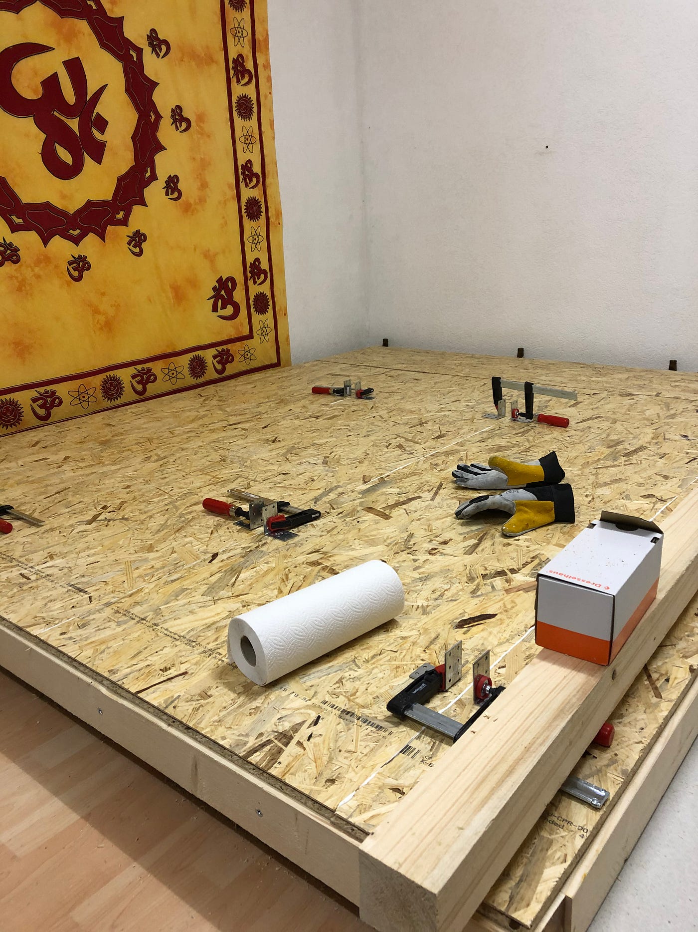
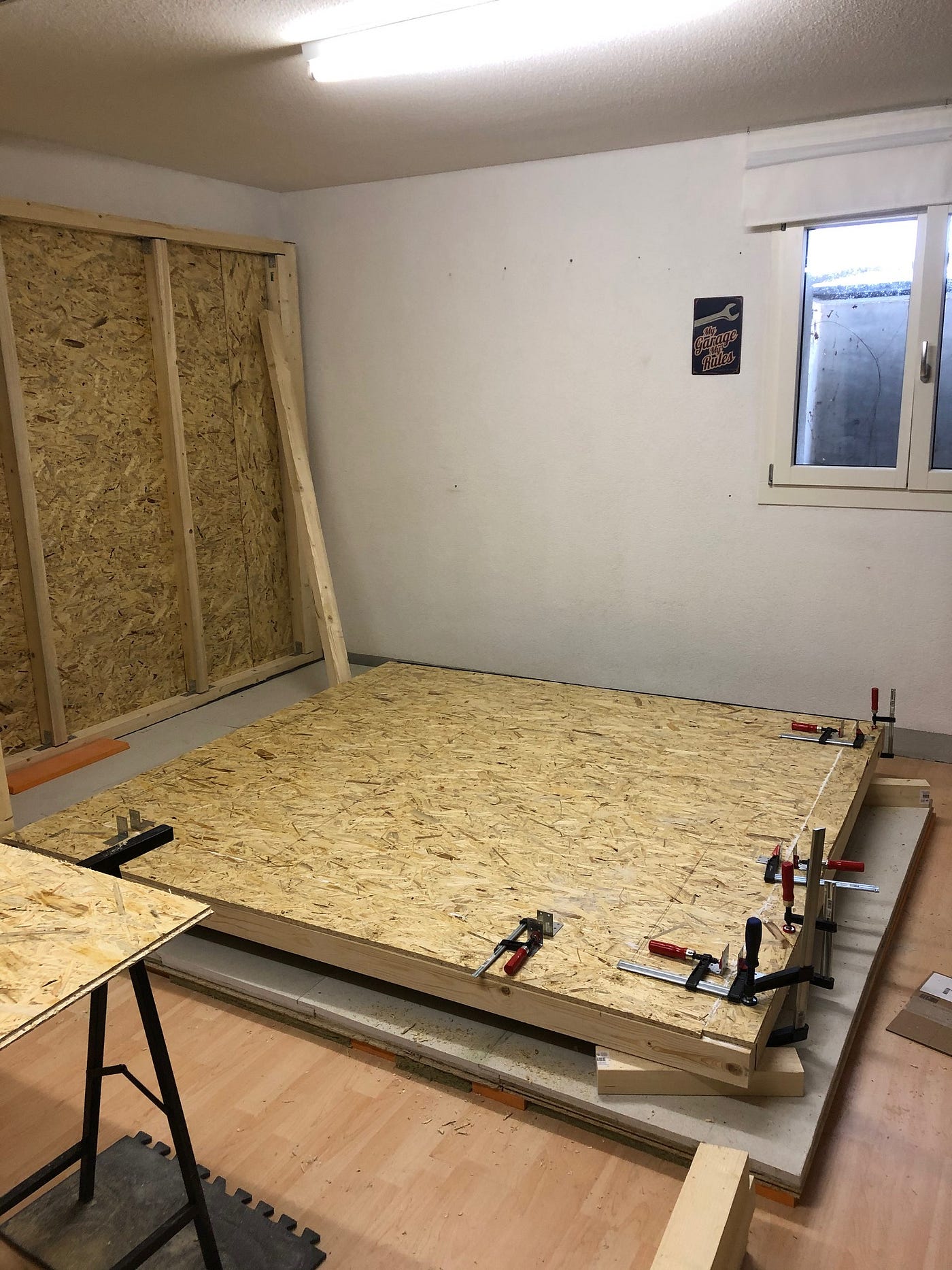
I used five 22mm thick, 650mm wide and 2500mm long OSB 3 chipboards for the base plate. The panels are glued together on tongue and groove and pressed together using screw clamps. I then fixed the plates with 5×40mm countersunk Torx screws.
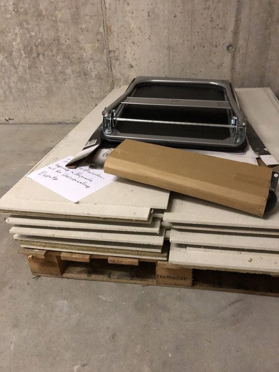
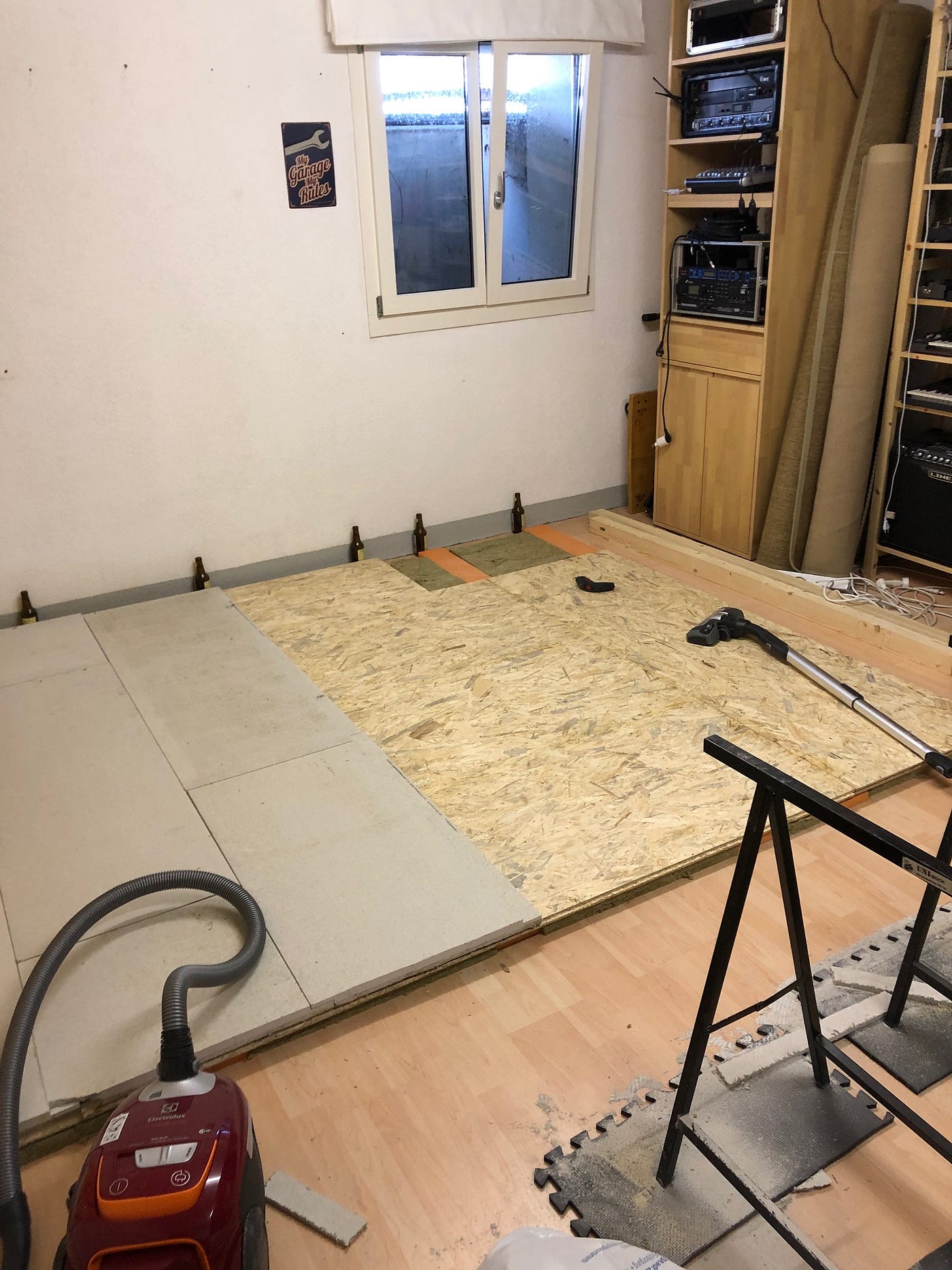
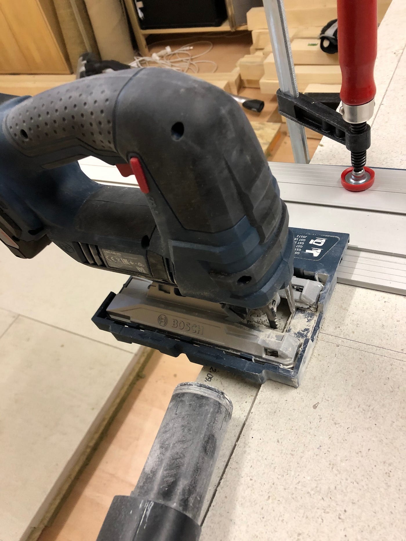
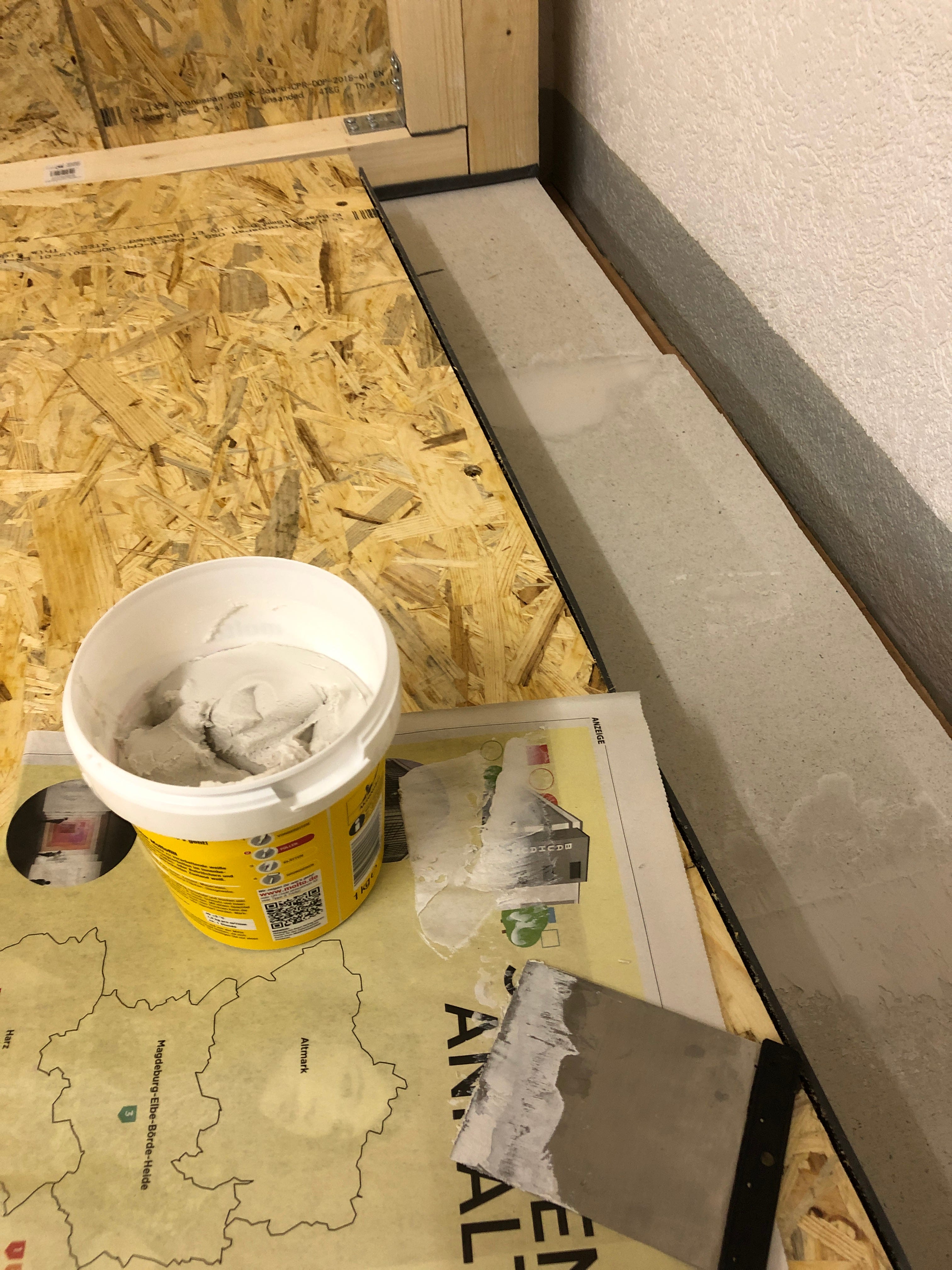
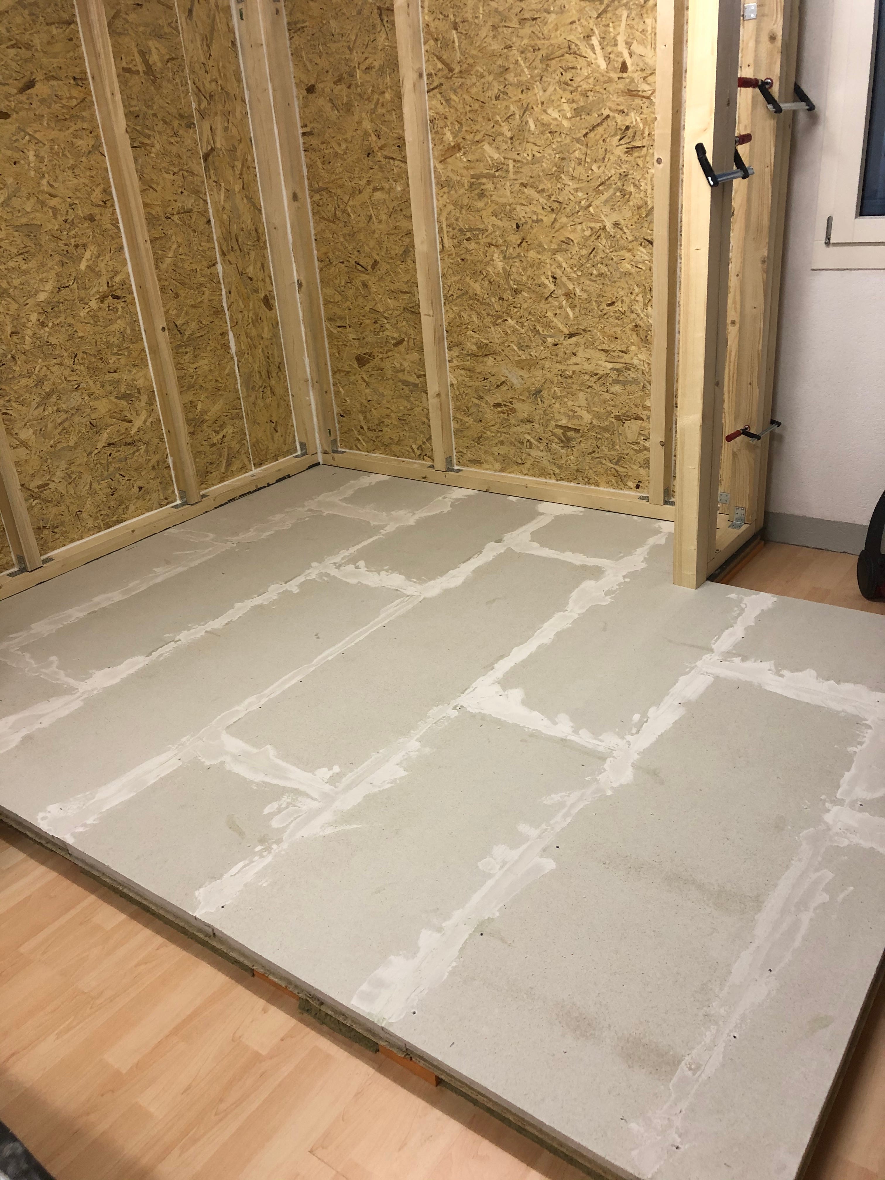
The third, mass-bringing layer, consists of Fermacell screed elements with an additional 10mm rock wool layer. The screed elements are laid fluently and must be sawn accordingly — quite a mess (respiratory protection required!). This caused my vacuum cleaner some serious trouble.
Attention: Before ordering the plates, take the exact dimensions into account. The plates are specified as 1550mm × 550mm, but they are laid 50mm overlapping — so the effective size is 1500mm × 500mm. I had ordered one panel extra. I was lucky!
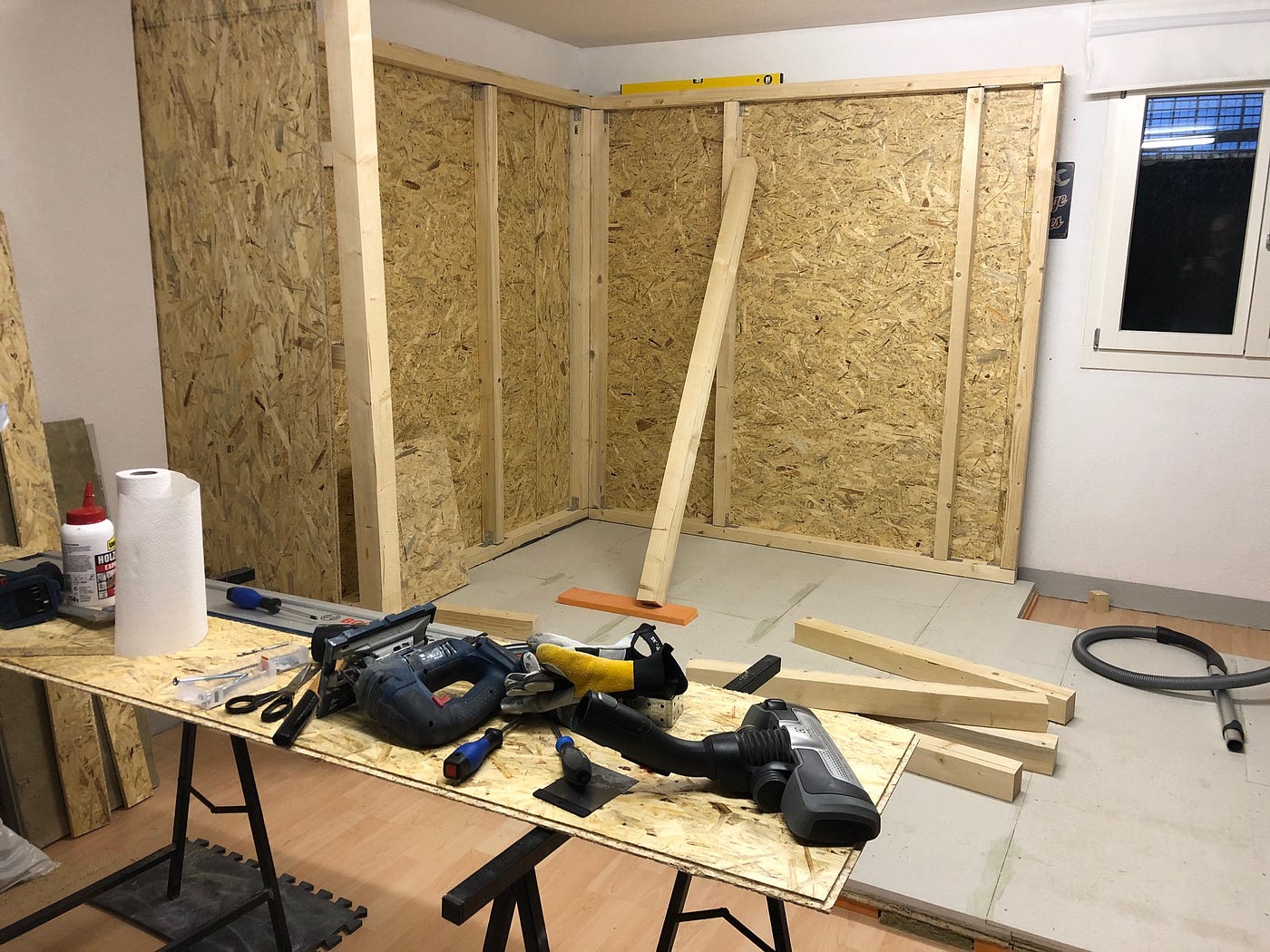
The Walls.
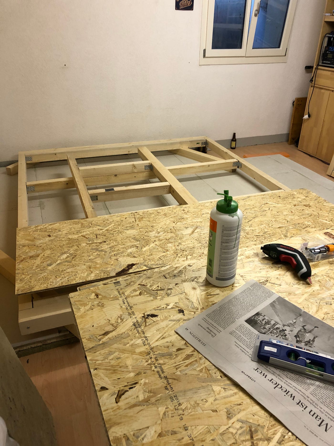
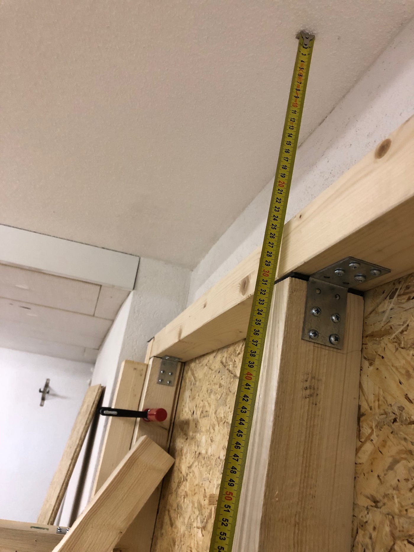
The structure of the sound cabin is constructed as a wooden stud frame. The frames of the walls consist of 60mm × 80mm squared timbers, which are screwed to 80mm × 80mm corner posts (6 of them). I use the thinner squared timber for the frames to save some weight.
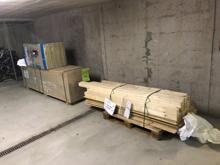
I ordered the beams for the side walls online and had them cut to size. My experiences are thoroughly positive — the cut is accurate to the millimeter and no bar was crooked or of unsatisfactory quality. The time saved by the already sawn timber is considerable.
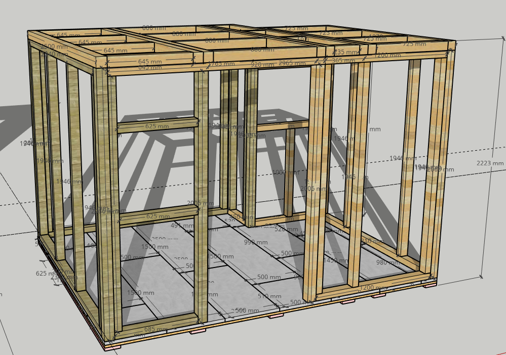

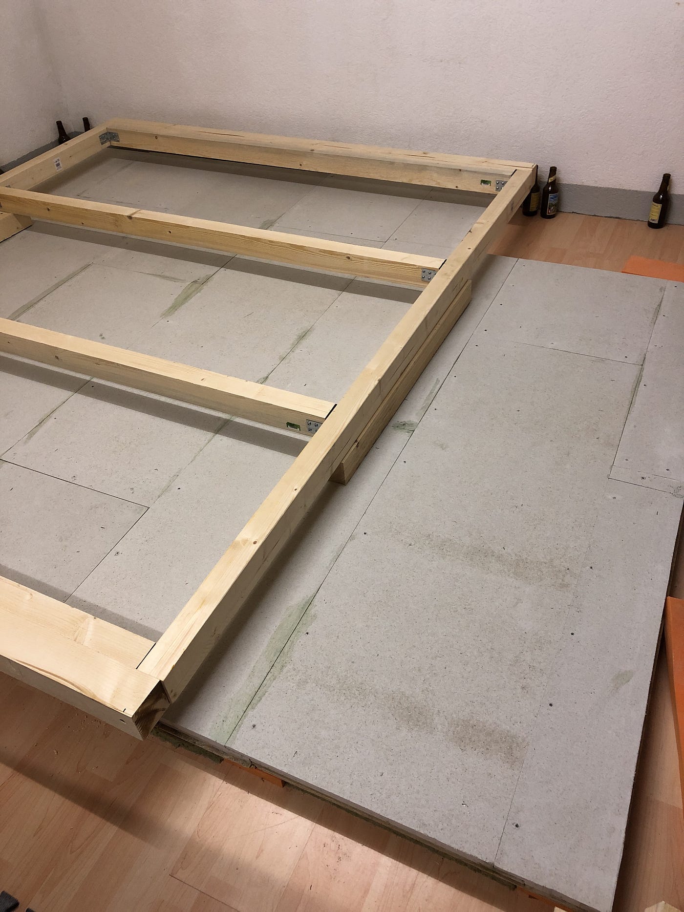
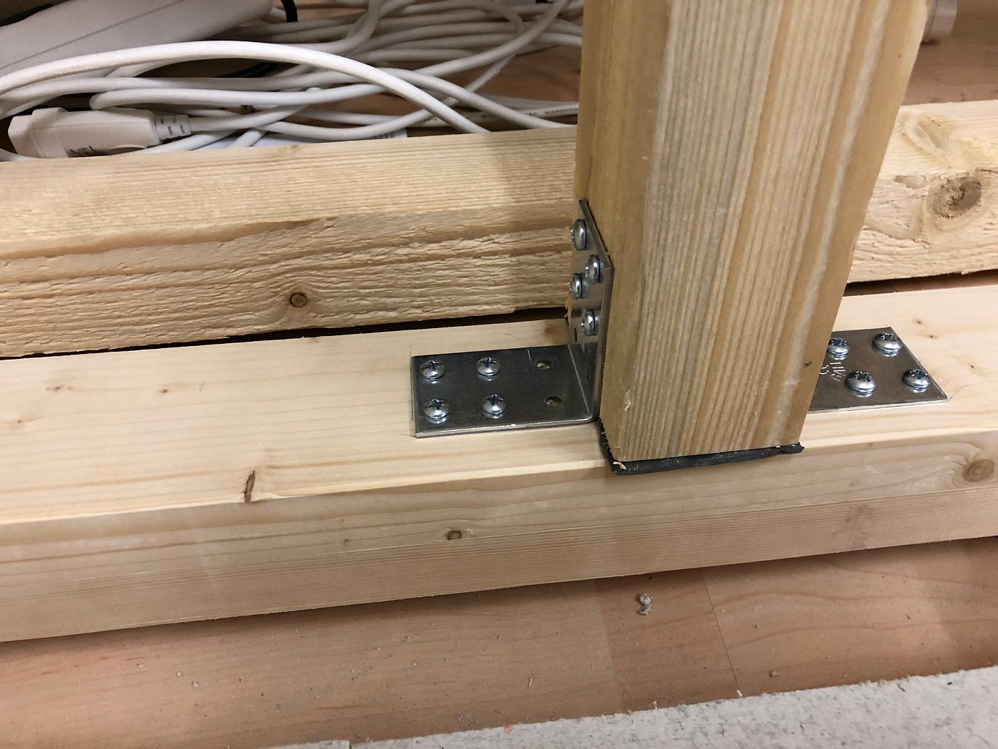
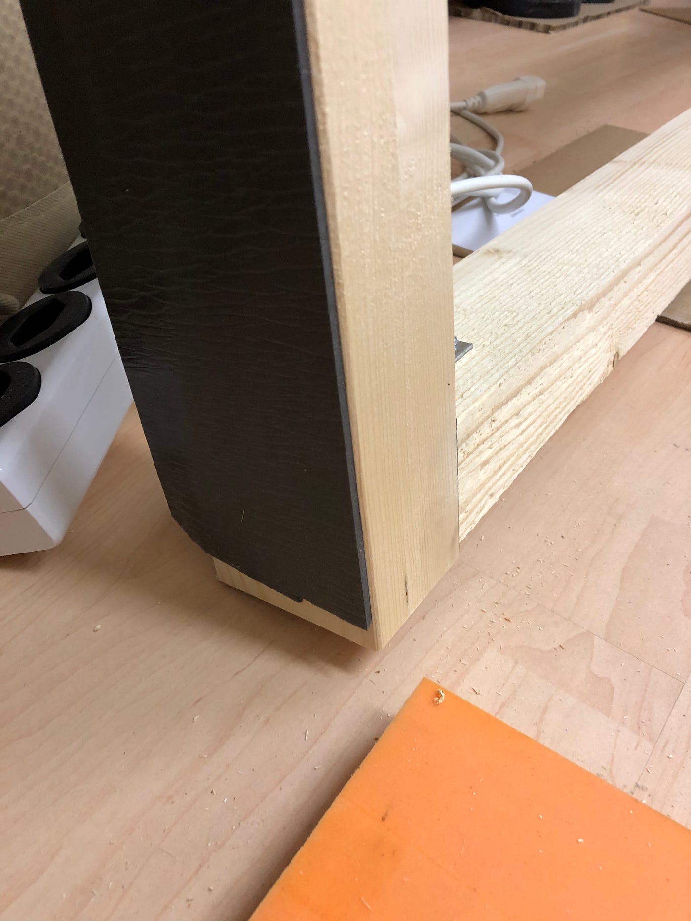
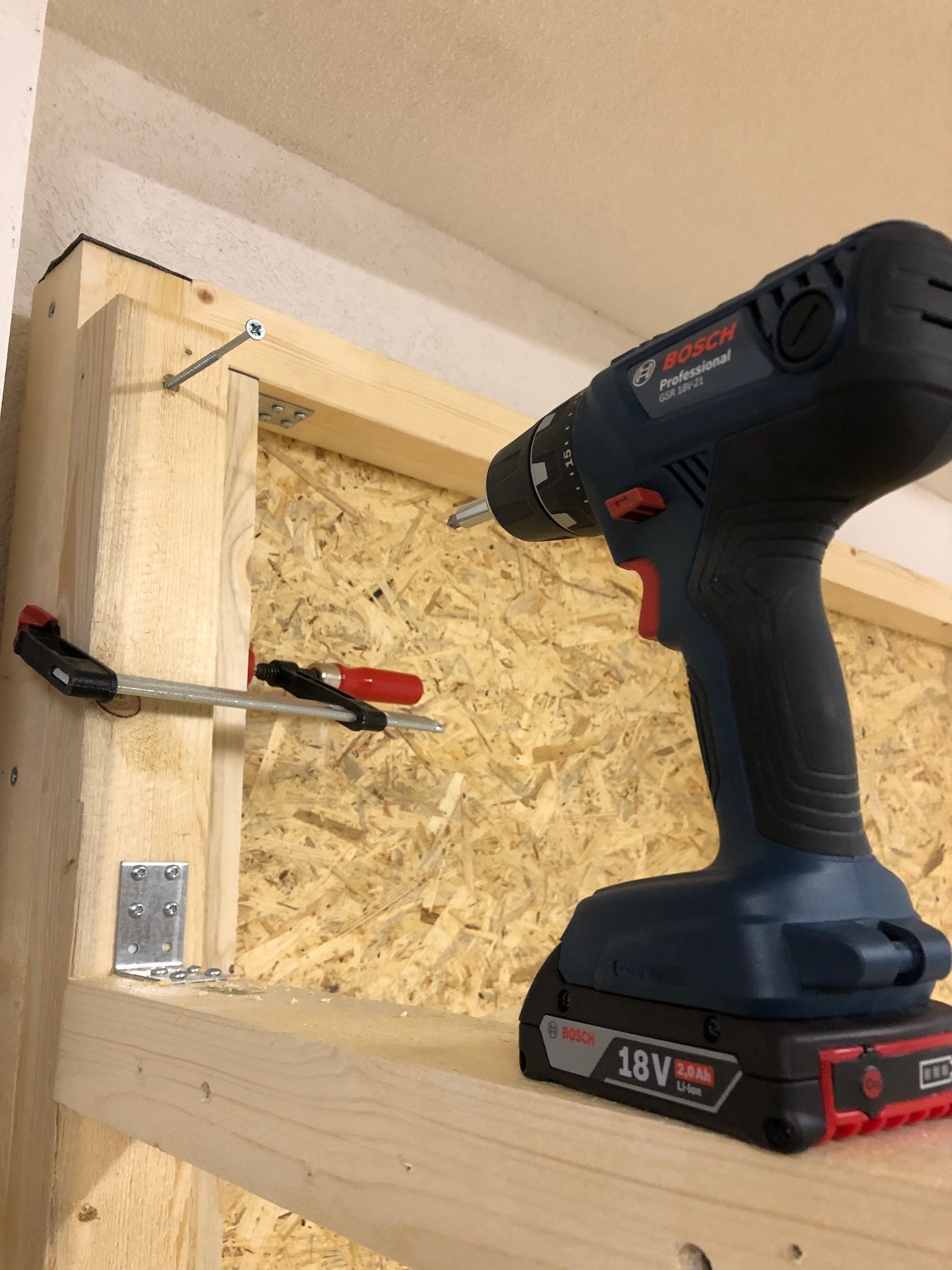
The woods are connected via metal angle connectors and 3.5×40mm pan head screws. I glued all the posts and struts with sealing strips at their vertical contact points for acoustic decoupling. Incidentally, the scaffolding is not screwed or glued to the floor.
I used OSB 3 boards 625×2050×15mm for the planking. I would have preferred 22mm plates, but had to keep an eye on the total weight. The panels are glued on tongue and groove, pressed together with angle connectors and clamps, then fixed with 5×40mm countersunk Torx screws.
So that there are no joints and audio snippets do not find a way out, I will later seal all connection points (boards/beams, beams/floor, beams/beams) with acrylic.

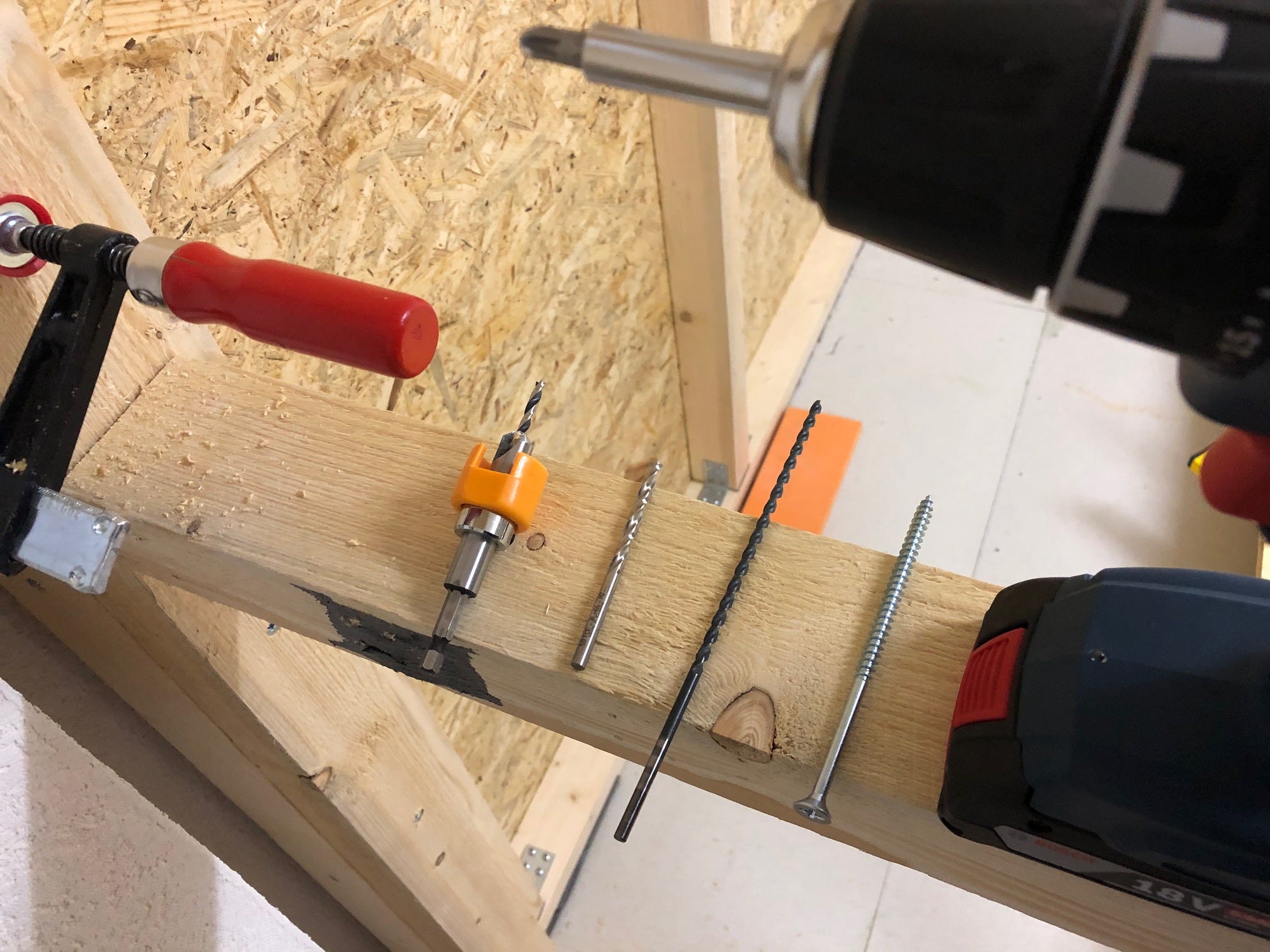
The walls are connected to each other via corner posts and 6×12mm countersunk screws. Nothing works here without pre-drilling — wood drilling is developing into a real passion.
As a final step before building more walls, the joints in the walls and the floor slabs need to be sealed. I use acrylic sealant for the panels and beams of the walls, and Moltofill depth filler for the floor panels.
Metal over wood.
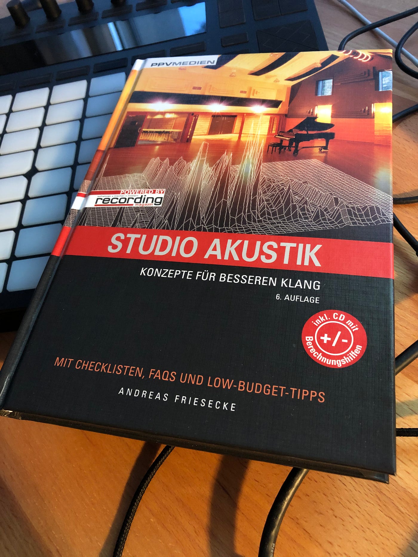
When I mentioned my sympathy for working with wood in the introduction, I was looking for another justification: namely the supposedly better sound absorption from wooden stud walls. However, I recognized the misconception after consulting my favorite book on the subject. Drywall stud frames with metal profiles and plasterboard cladding do a much better job with regard to absorption.
Since metal profiles weigh up to 1/4 of the weight of the square timbers used in my case, the saved weight can be invested in additional formwork (more/thicker panels). Different material, different tools, different work steps. I still like working with wood — but the weight savings are considerable.
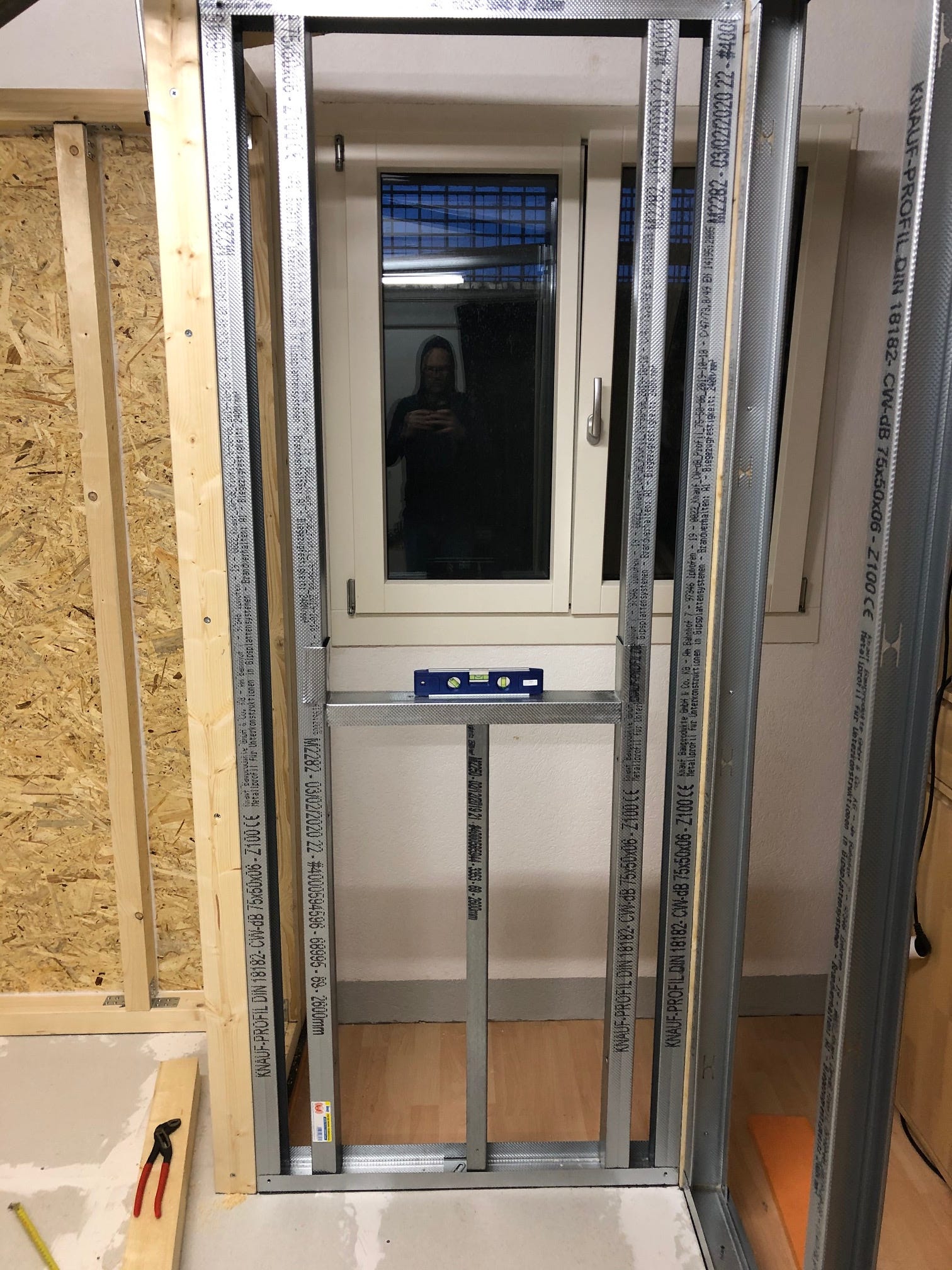
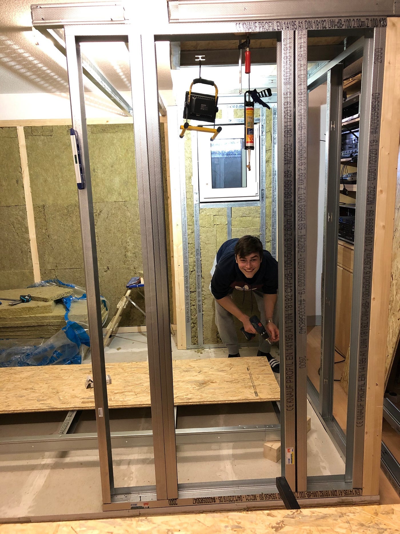
The first window.
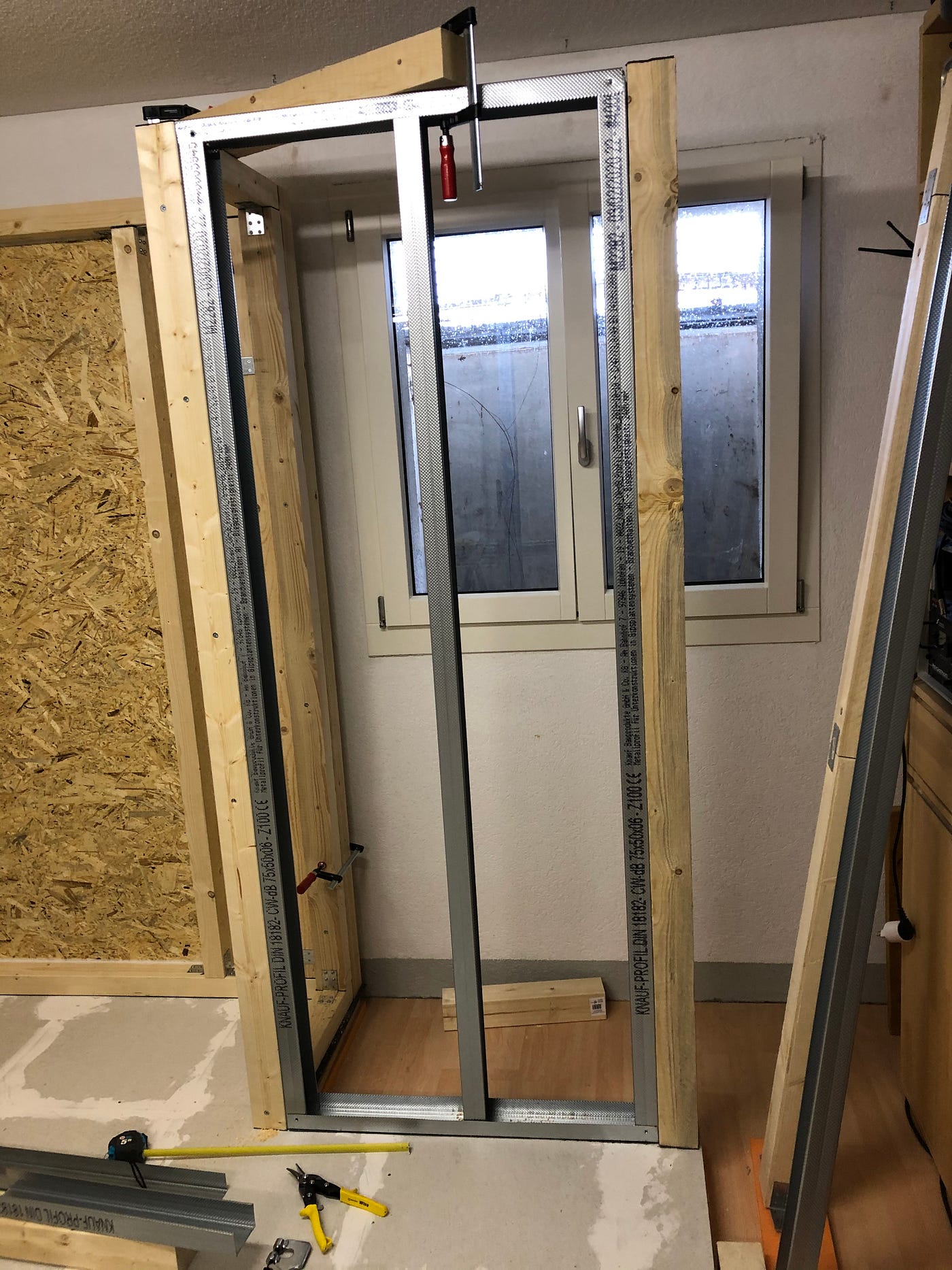
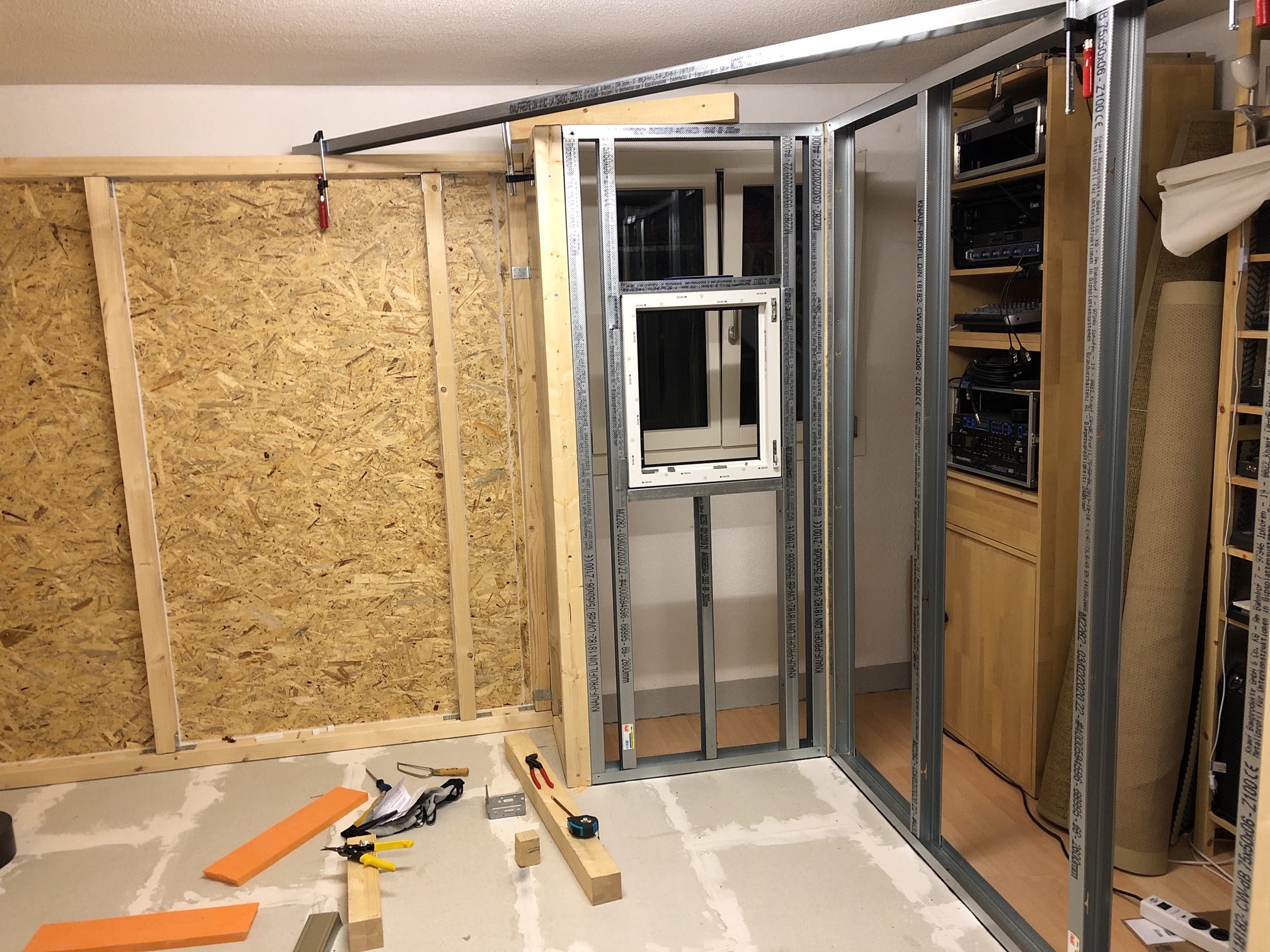
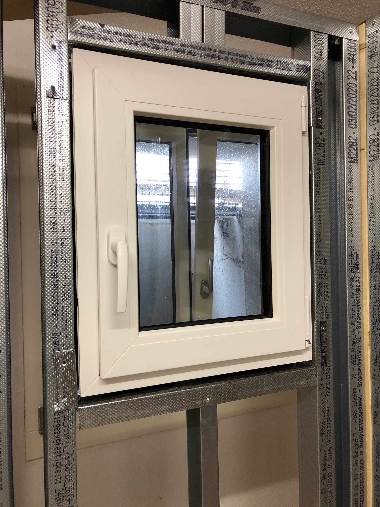
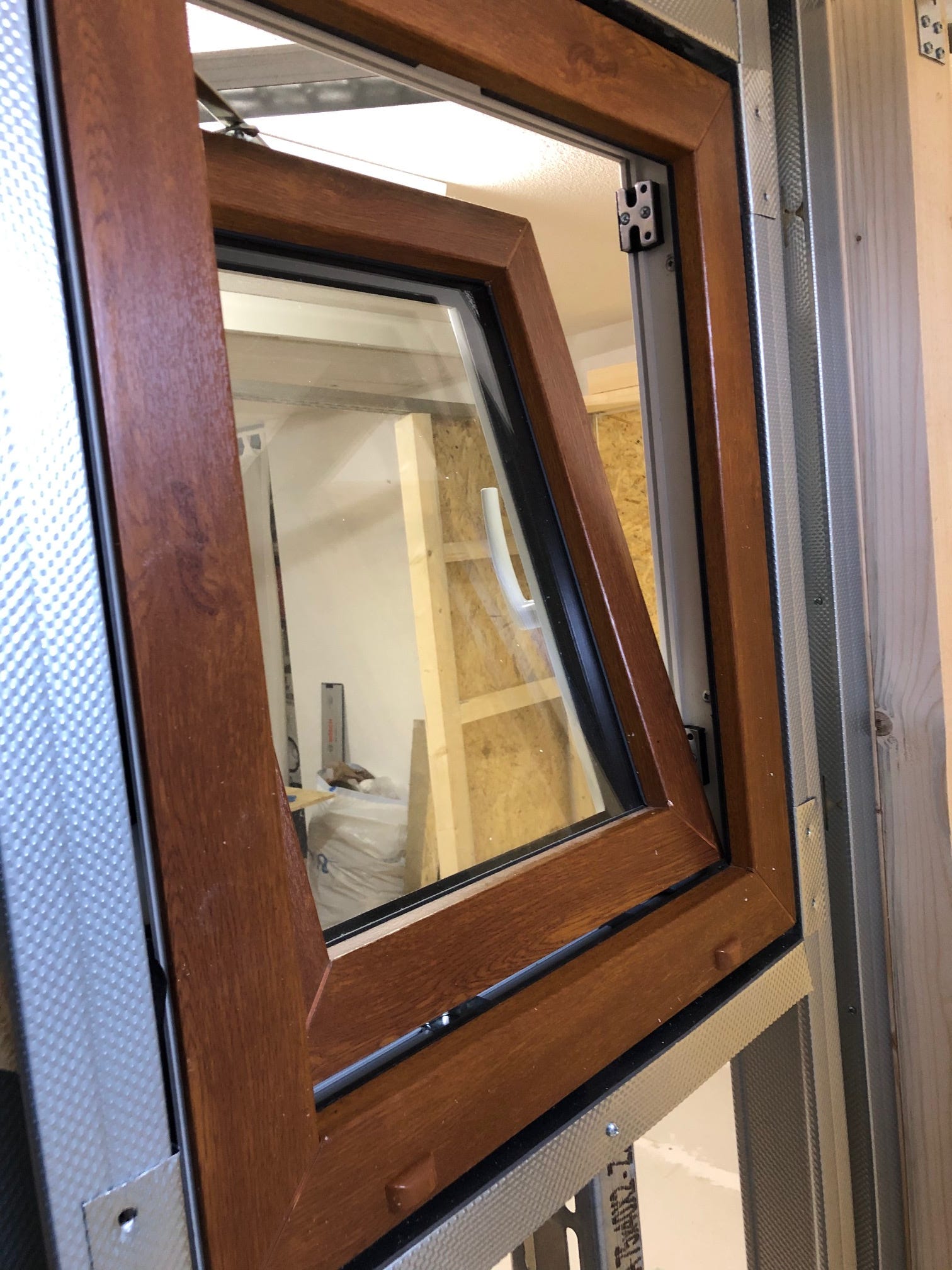
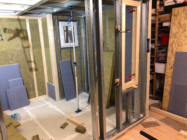
My first attempts using metal profiles are promising. Since I am waiting for more material, I started the installation of the first window.
The window to be installed is a triple-glazed 500×600mm prefabricated window from the hardware store. It is supposed to counteract a psychological "jail feeling" and allow access to the outside window. First I put two CW profiles in the window width in the frame. A 2mm UA profile in the middle under the window opening carries the weight. A UW profile, with an excess length of 10cm left and right and crimped with the CW profiles, forms the lower frame of the opening.
Like the lower frame, the lintel is cut from a UW profile that overlaps 10cm on both sides. I sawed a longer UA profile later because the window was a little too low for me.
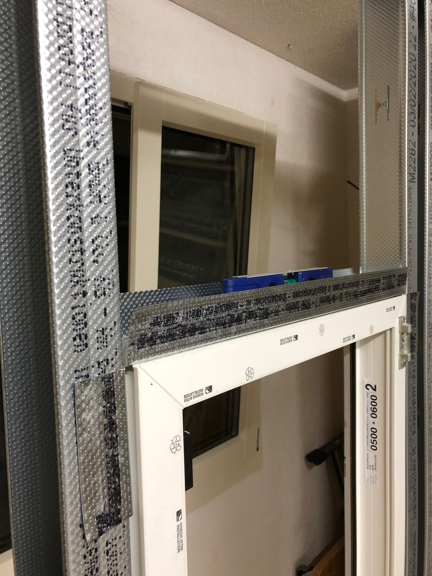
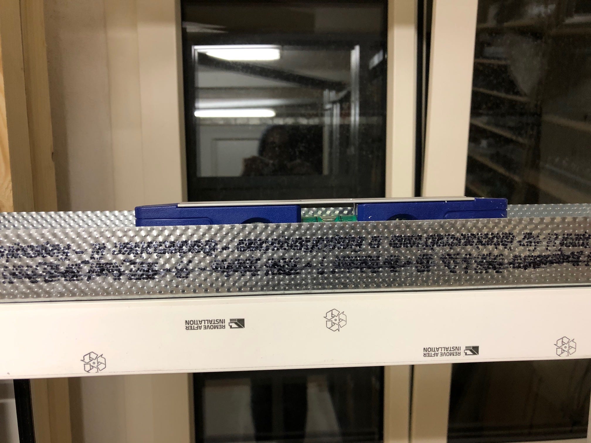
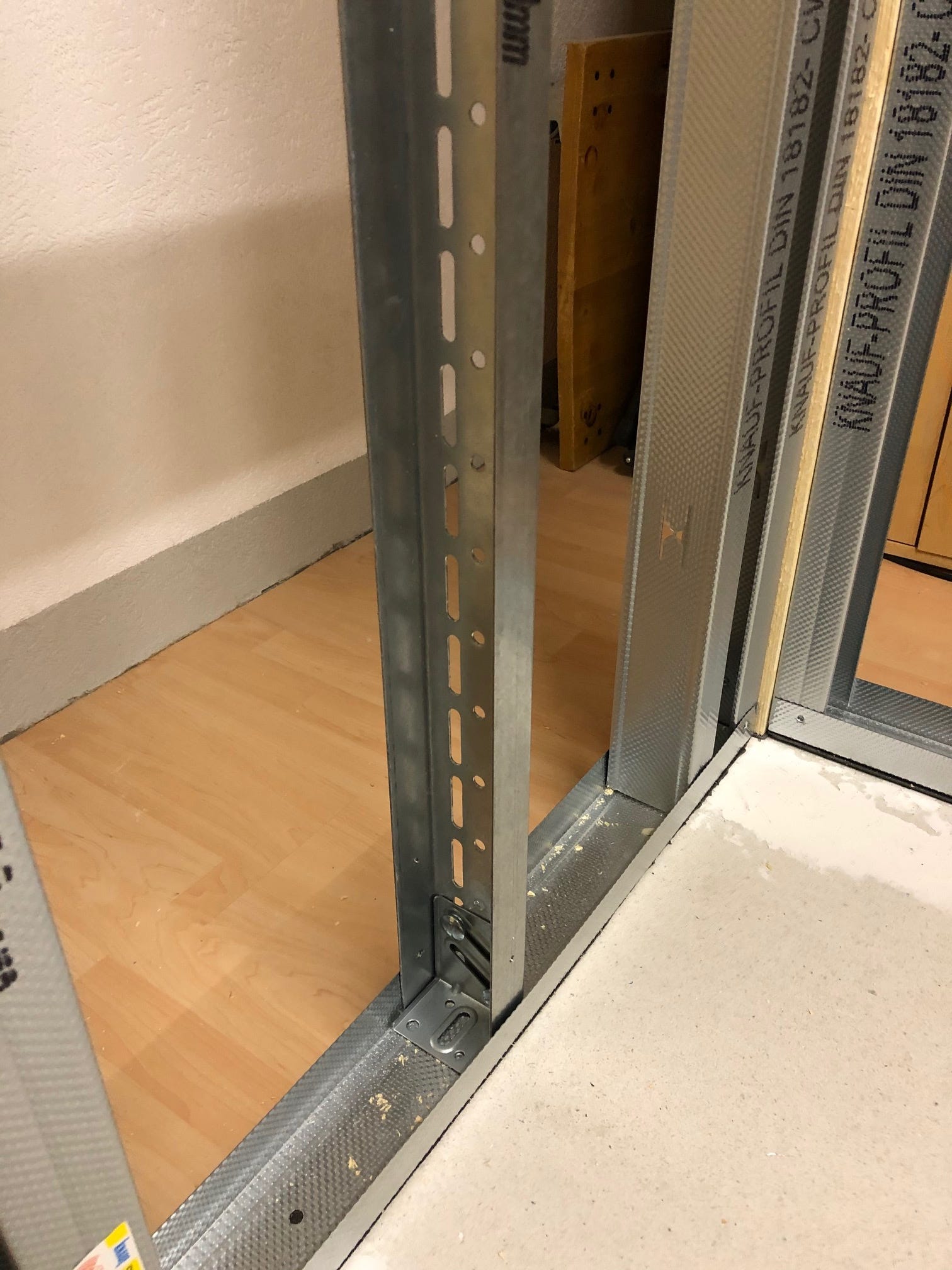
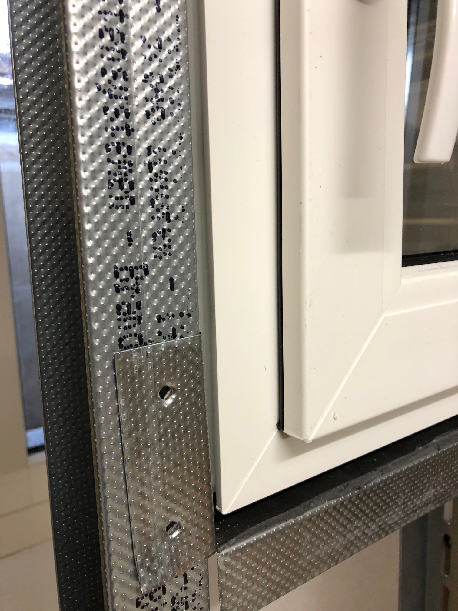
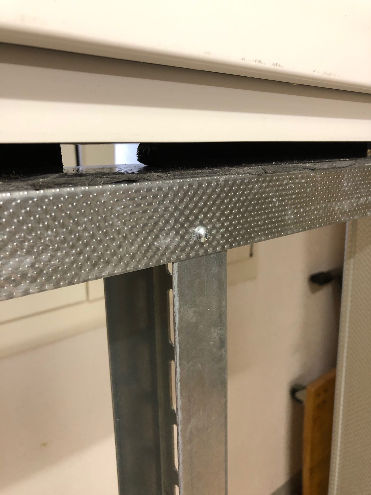
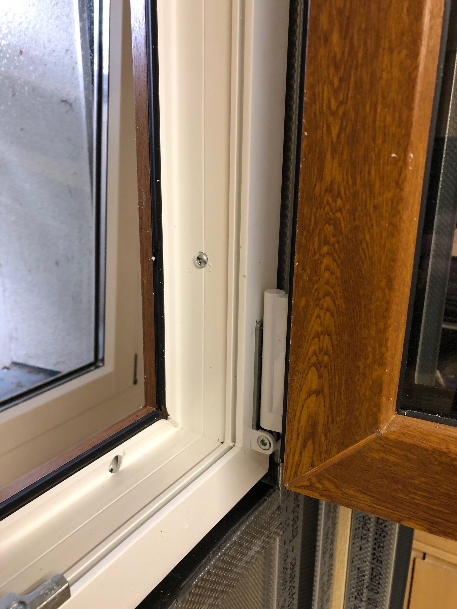
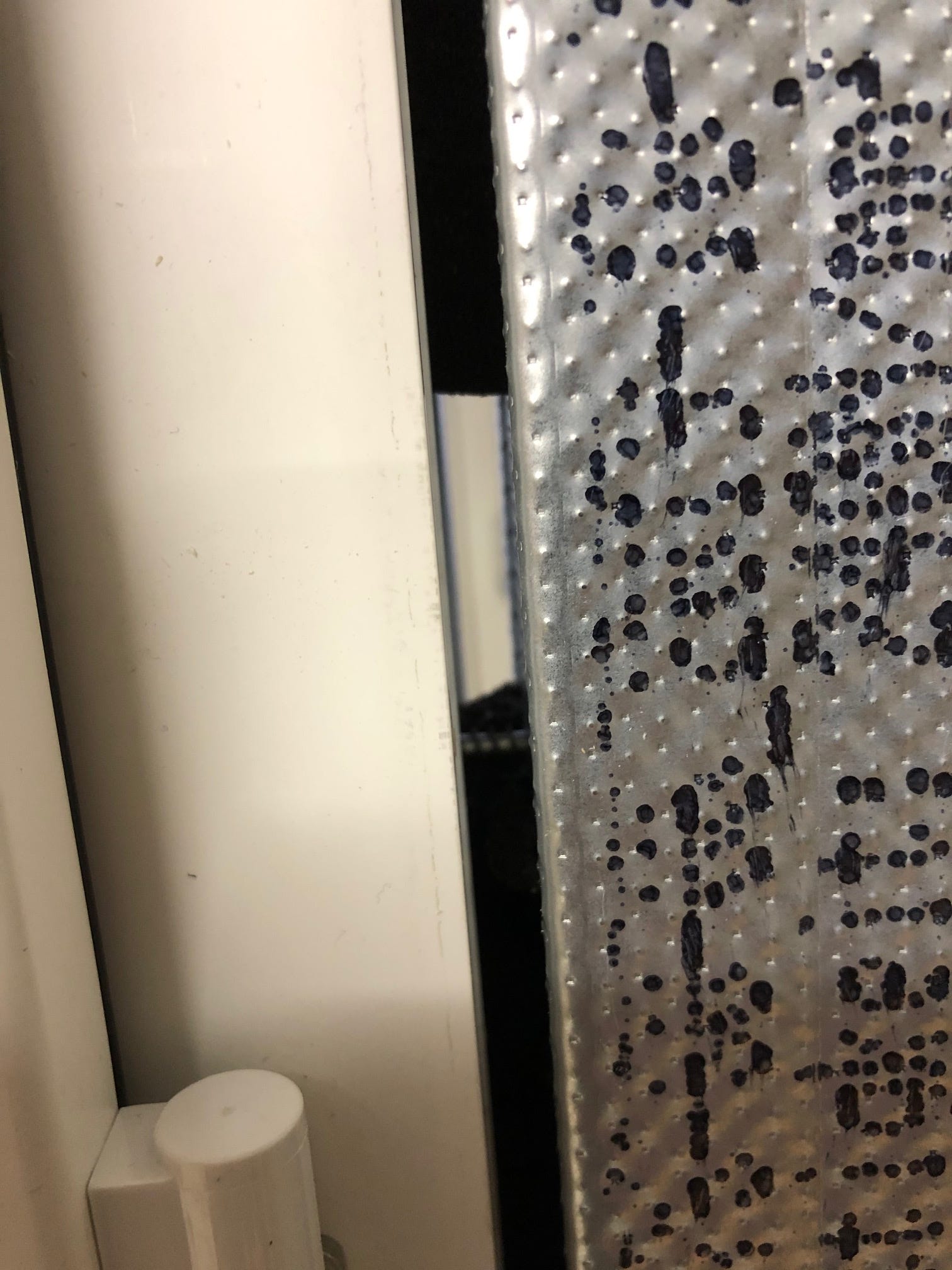
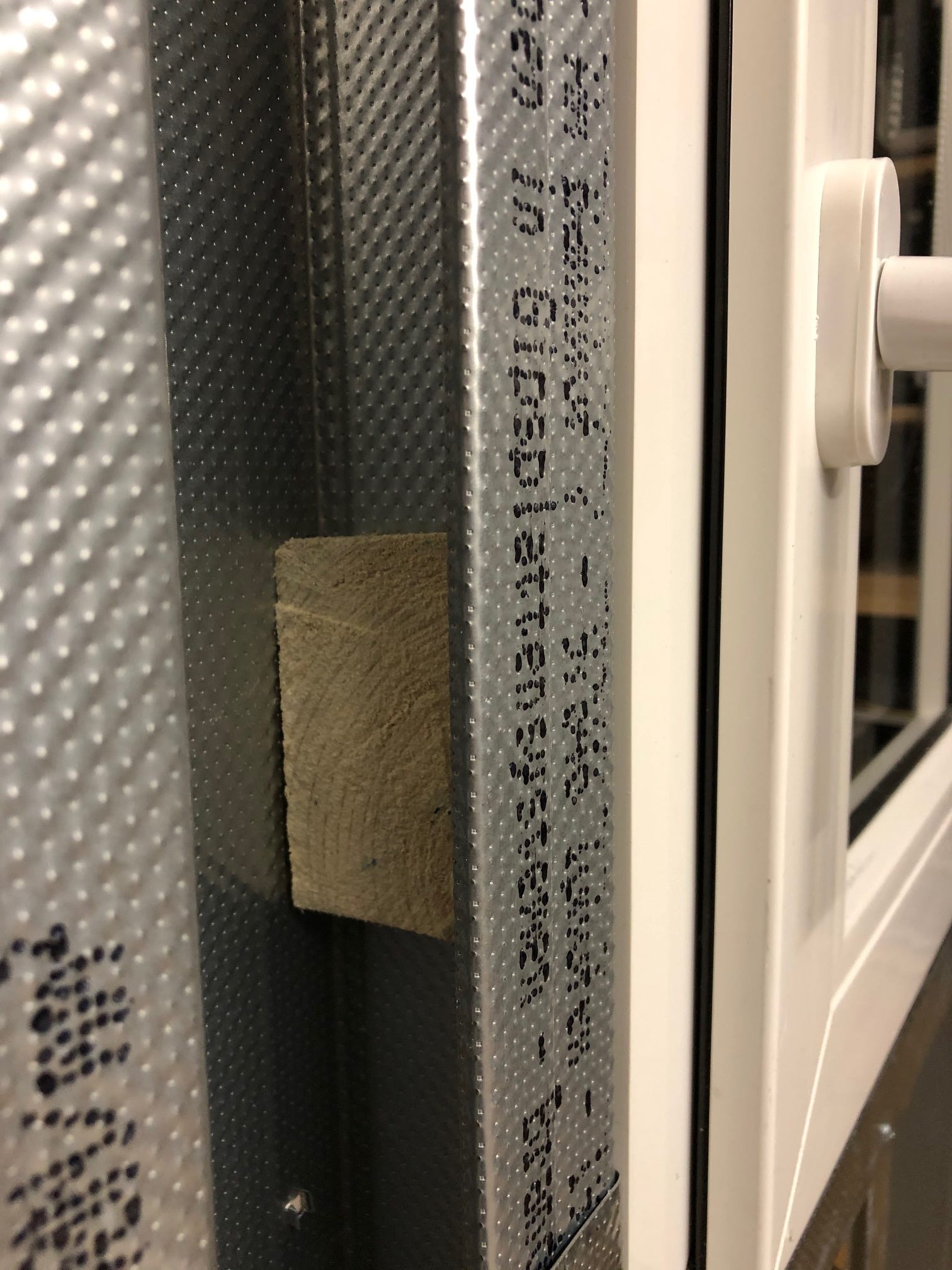
I used sealing tapes to fix the window. Once glued from the roll and onto the window frame, the material massively increases in volume, presses the window frame against the metal profiles and thus stays in position. I also drilled two holes through the frame on each side and screwed it to the metal profiles with wood screws — with added wooden blocks for better grip.
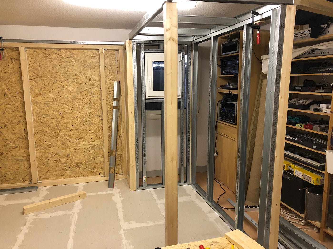
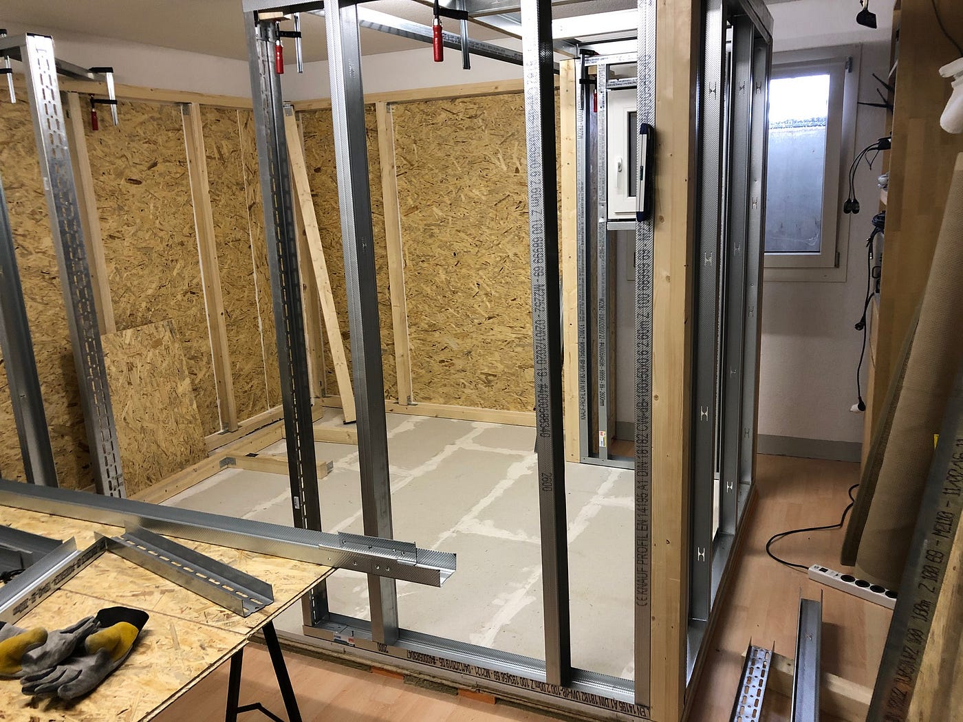
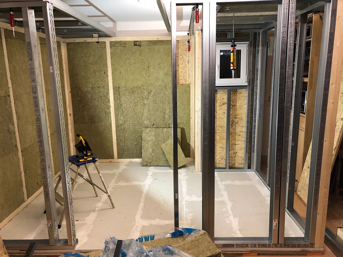
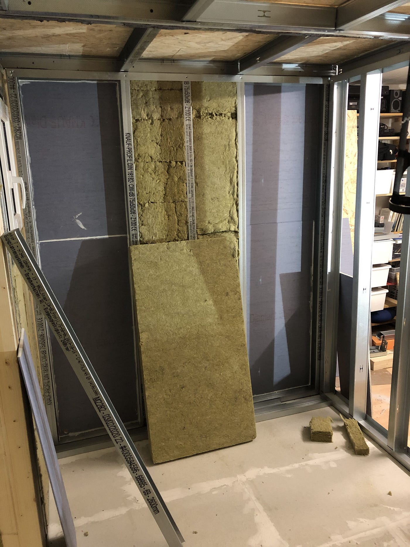
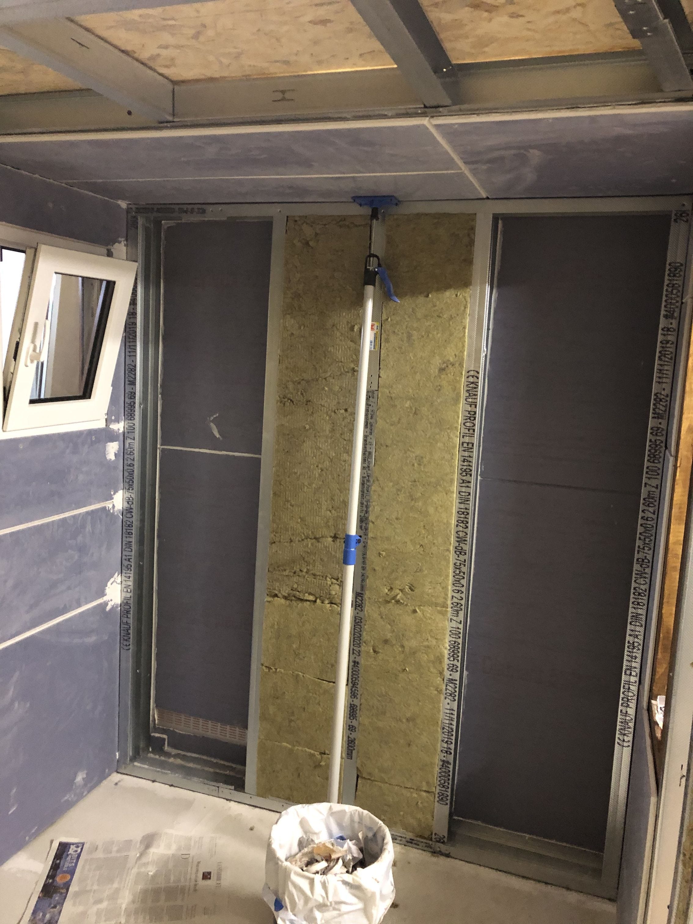
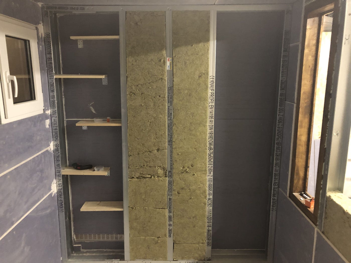
Metal profile walls.
A real difference to working with wood is that the unplanked metal profile walls are initially much less stable and have to be temporarily supported more often. Gazelle-like sneaking is necessary so that the whole clutter does not collapse during assembly.
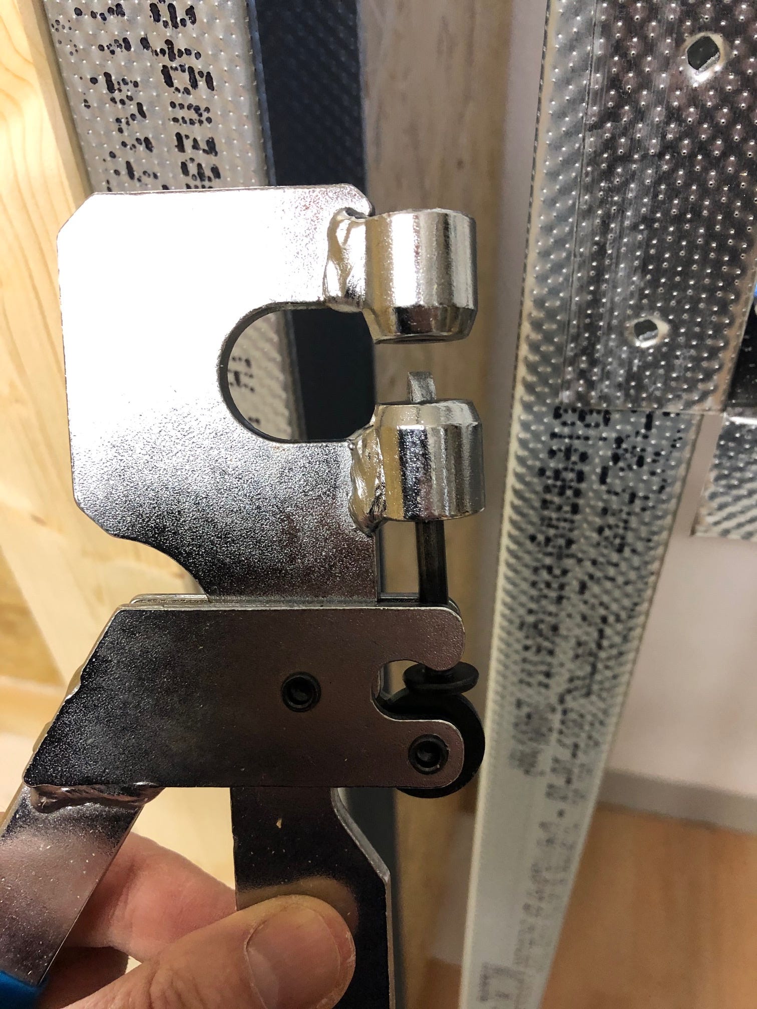
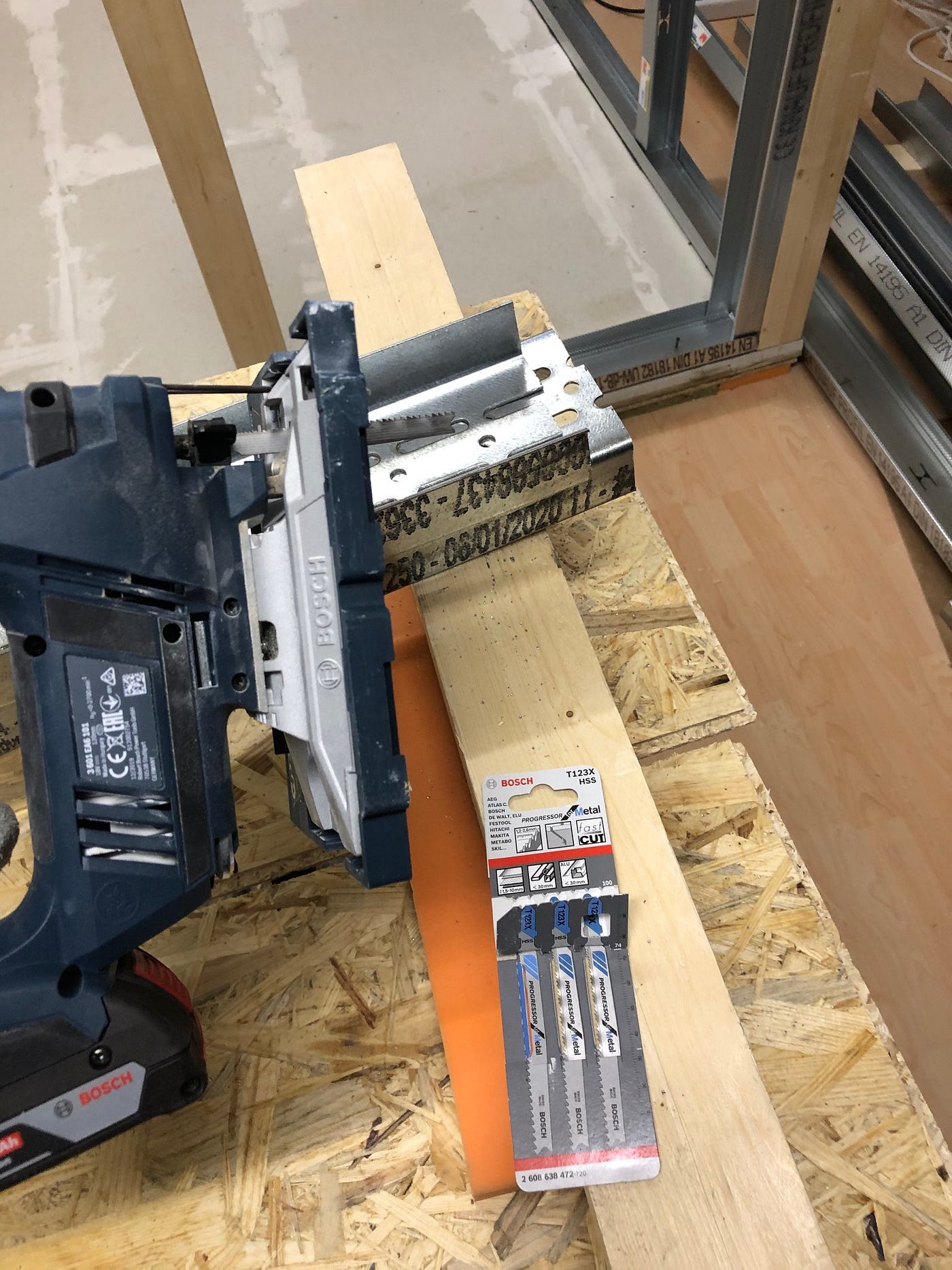
The 2mm stiffening profiles (UA) can no longer really be processed with tin snips. With a hacksaw by hand, or appropriate blades for a jigsaw, it works — quite well, but slowly. The front wall, which is supposed to house a soundproof door and another window, is constructed with 100mm profiles (in contrast to the 75mm profiles of the ceiling and the other walls).
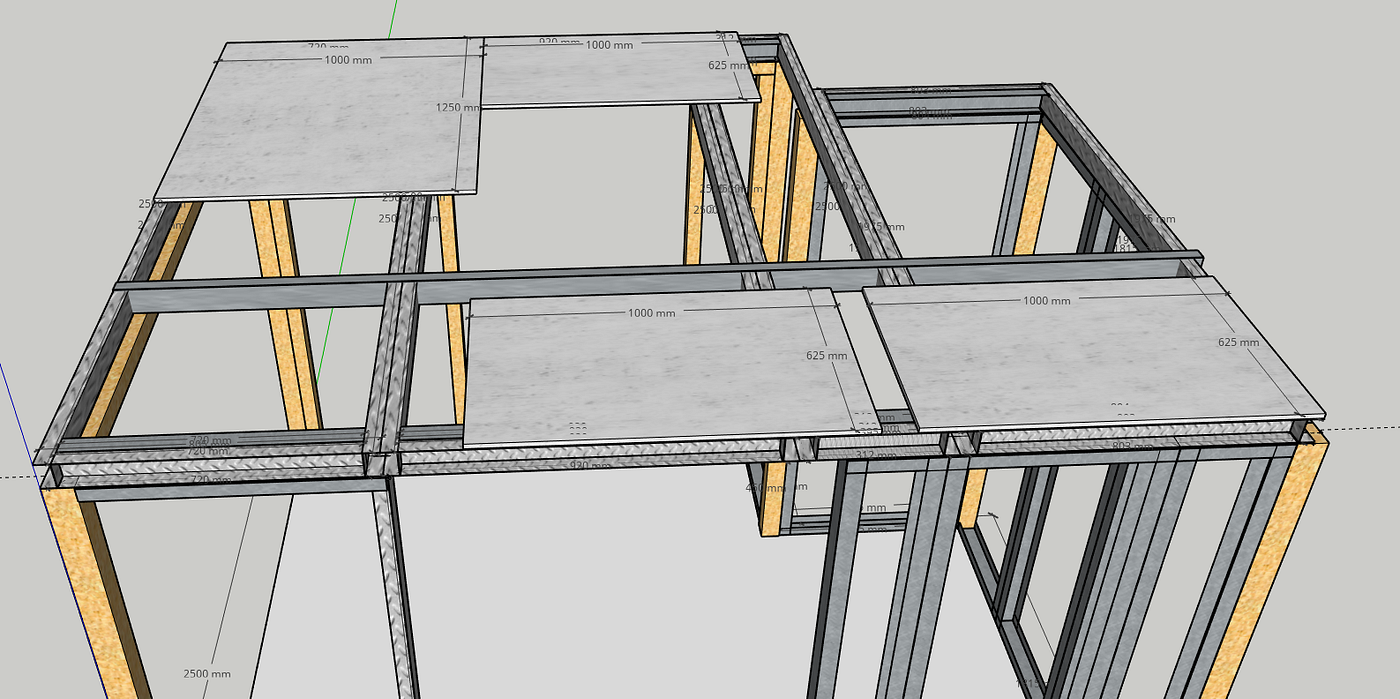
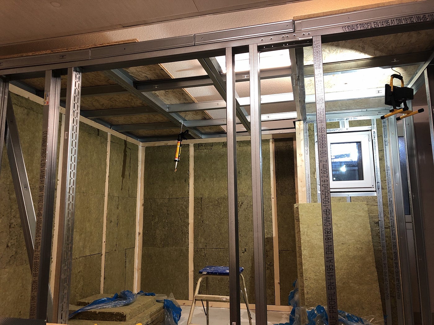
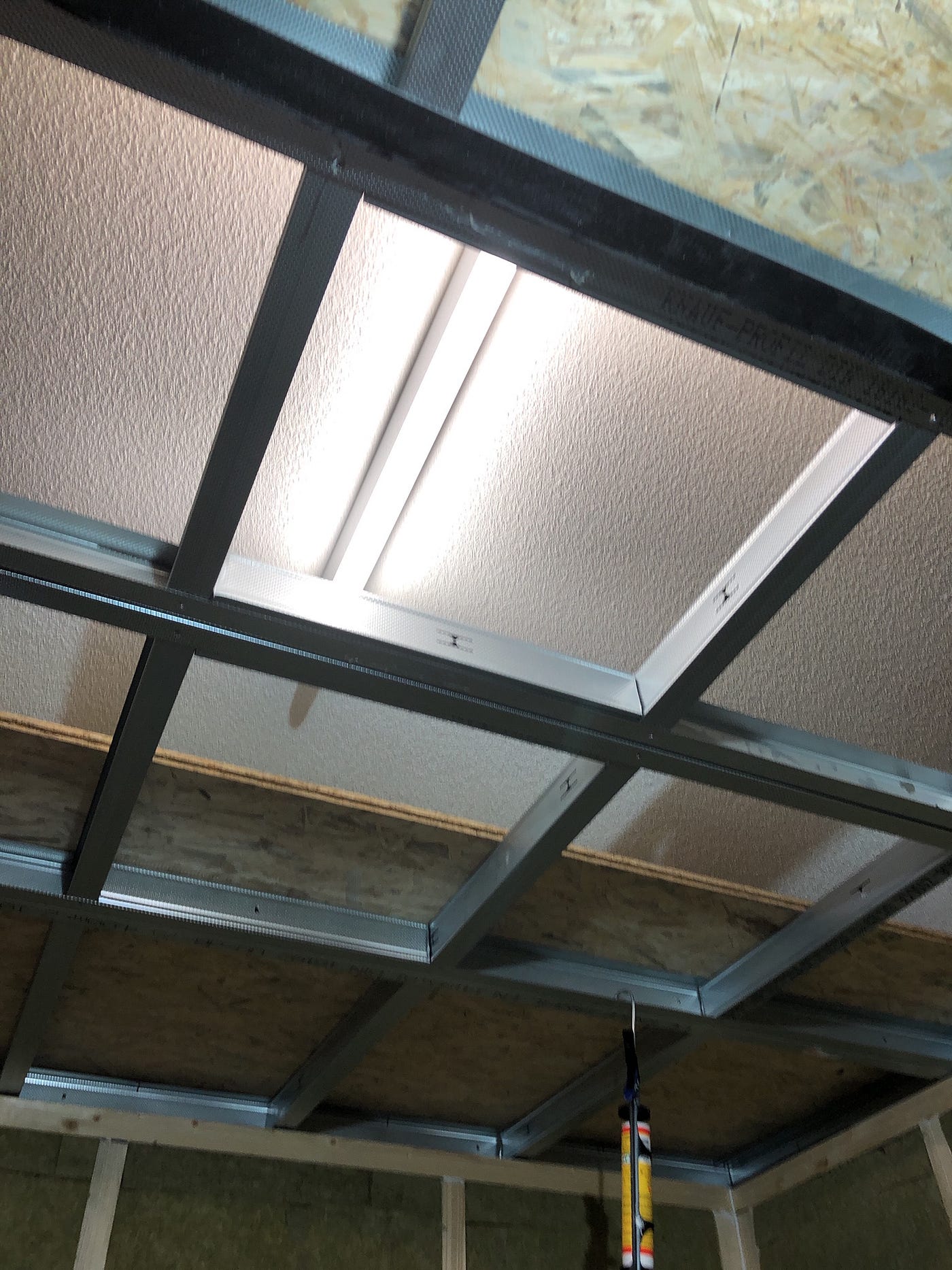
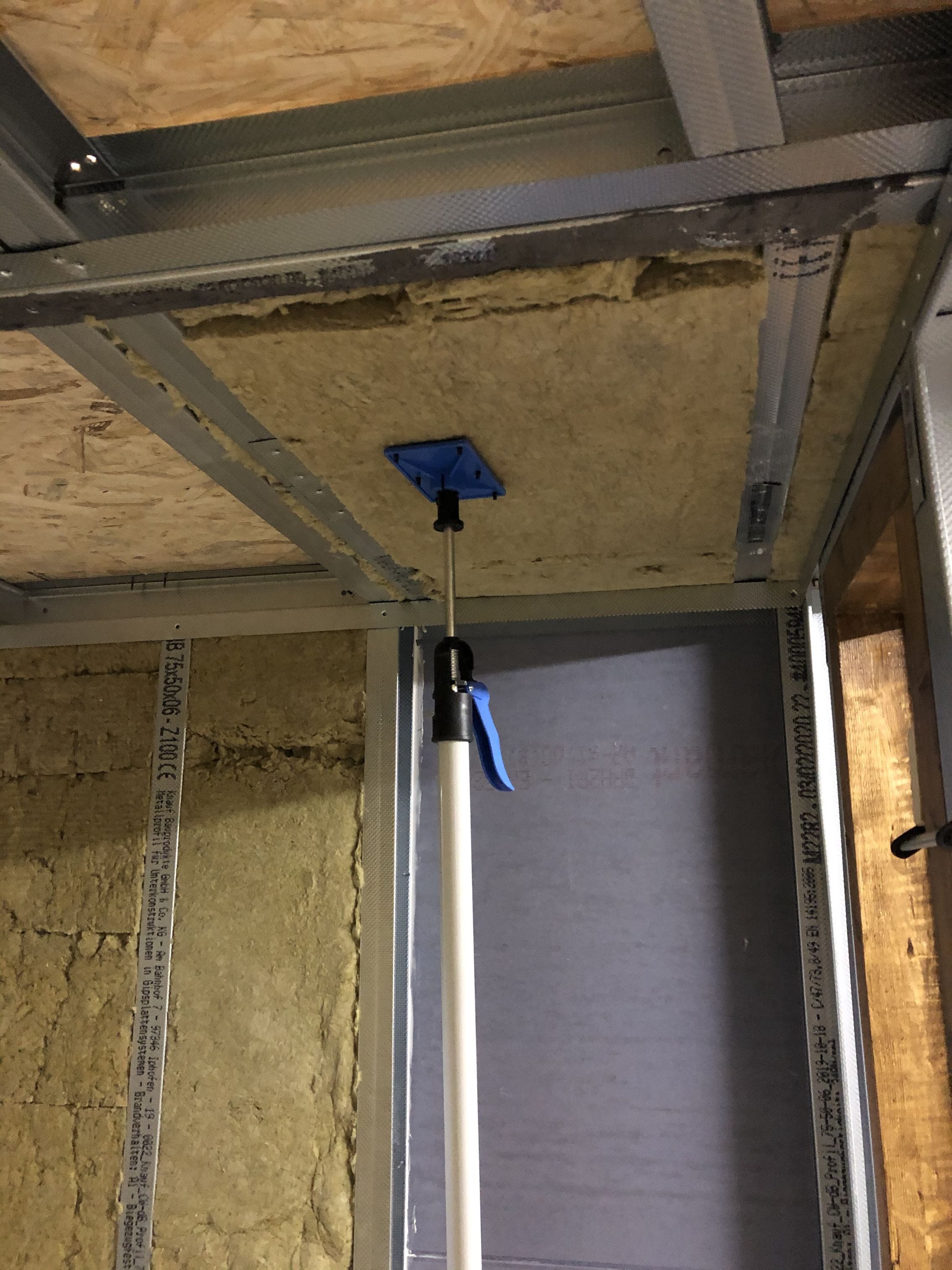
Building the ceiling.
Since I am no longer the youngest and have less to oppose gravity than before, I planned the ceiling in modules. The modular structure is absolutely necessary for reasons of space — the height of the outside room does not allow me to plank the ceiling from above. A completely assembled ceiling plus planking would be far too heavy and very difficult to assemble.
The modules are constructed from UW profiles in the longitudinal and CW profiles in the transverse direction. The formwork consists of 22mm OSB panels screwed to the profiles with drywall screws. Despite the greatest care, some ceiling modules are 2–3mm crooked. I hope to compensate for this with the external formwork, without negative effects on the insulation.
How do I get the ceiling light in the outdoor area if I need to replace it? I have provided two cutouts and made a kind of frame with CW profiles filled with mineral wool.
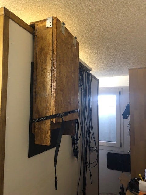
Soundproof ventilation.
Occasional breathing should benefit from the continuous supply of fresh air. So that this takes place without interrupting musical activity, soundproof ventilation is required. Somehow, air has to be constantly drawn in and out of the cabin without sound escaping.
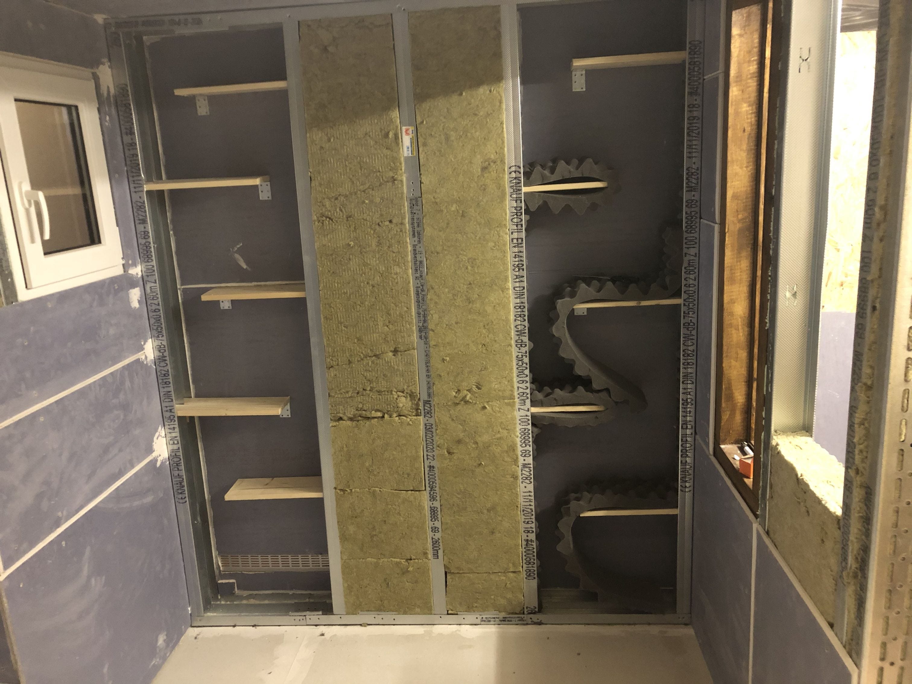
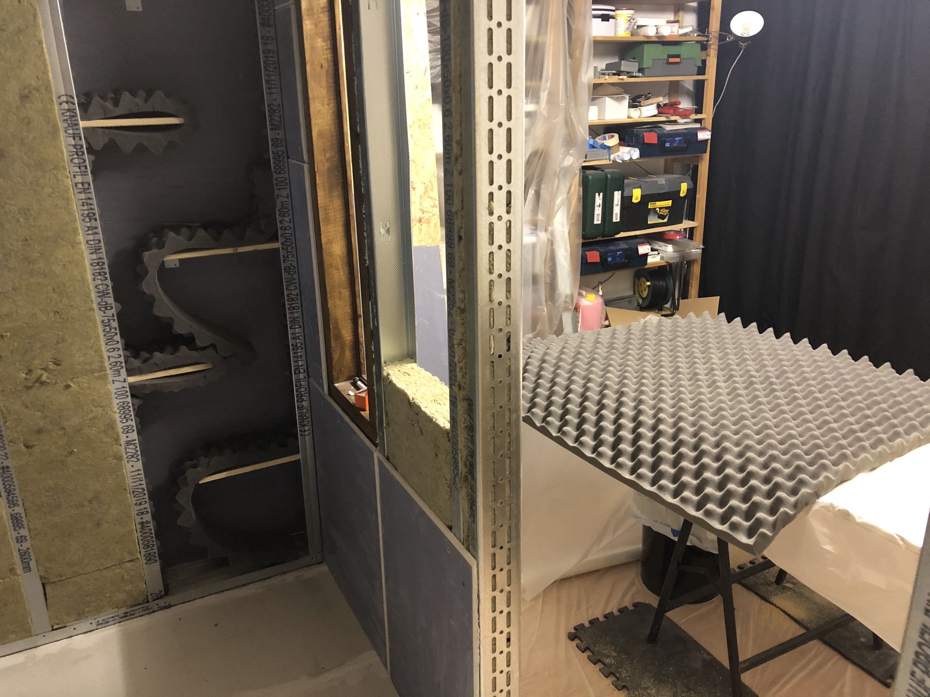
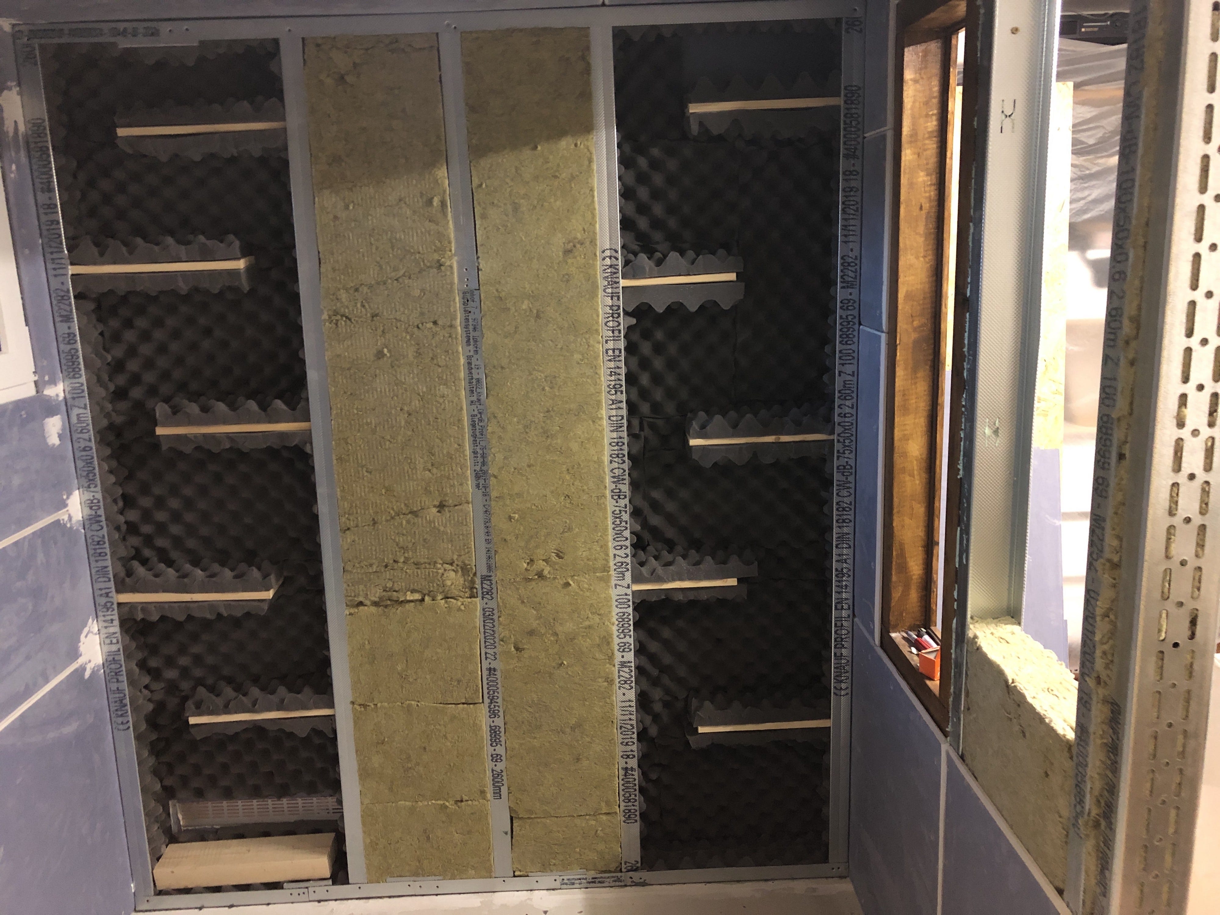
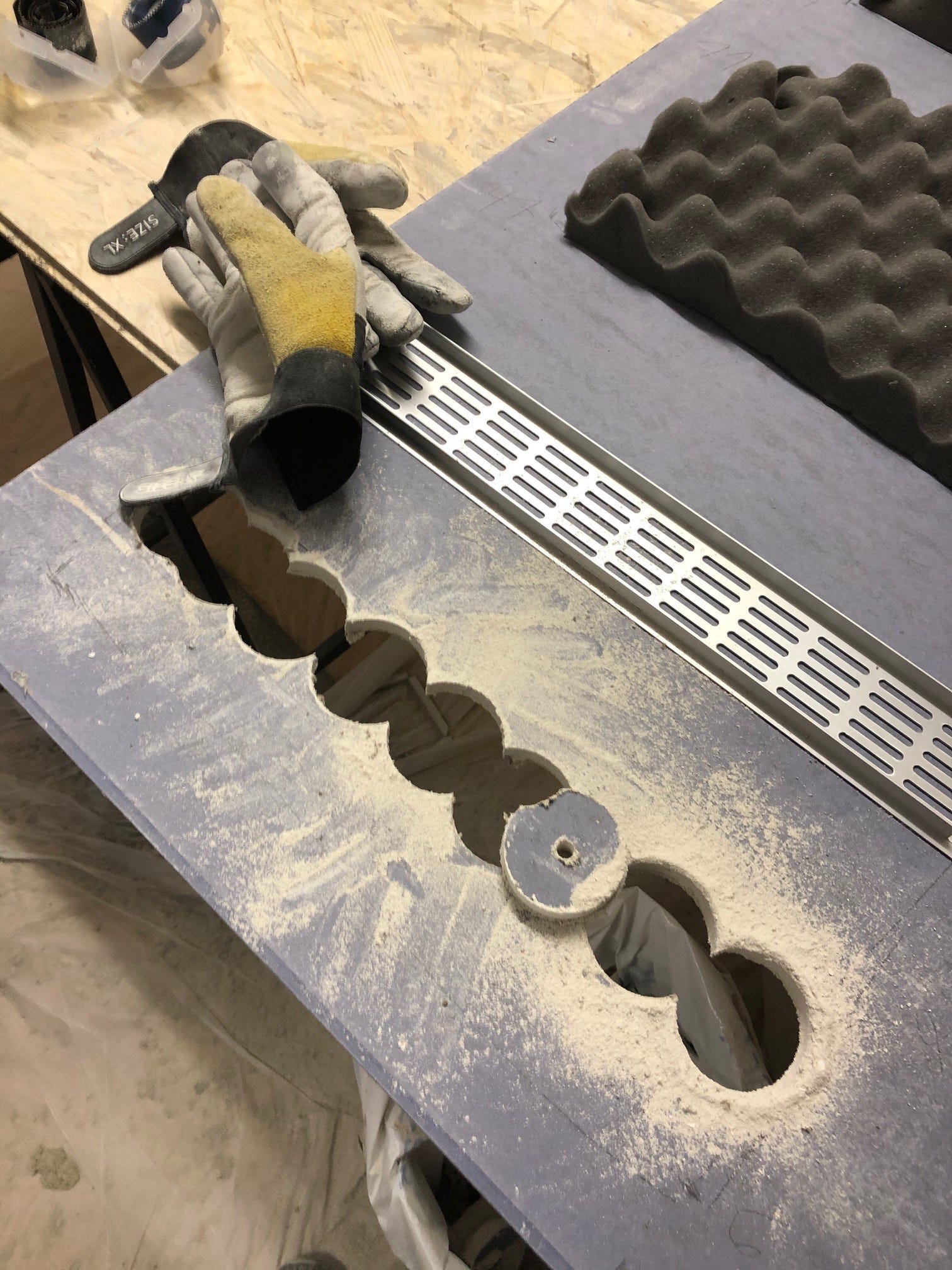
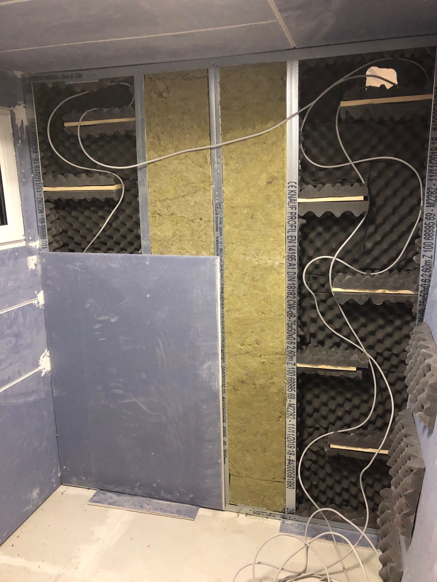
The construction consists of two shafts: on the left, warm air is drawn out of the cabin from below through a labyrinth; on the right, fresh air is drawn in in the opposite direction.
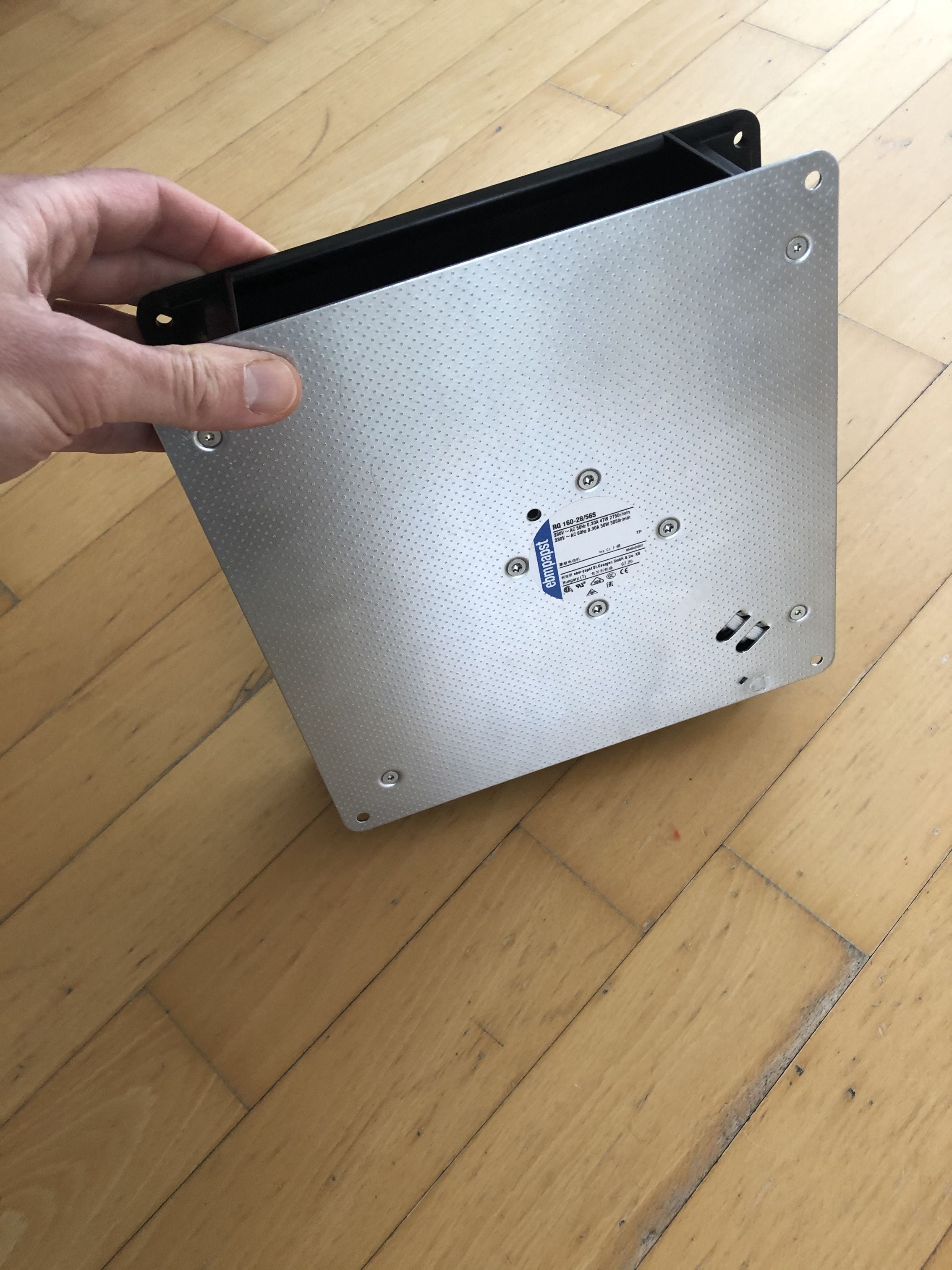
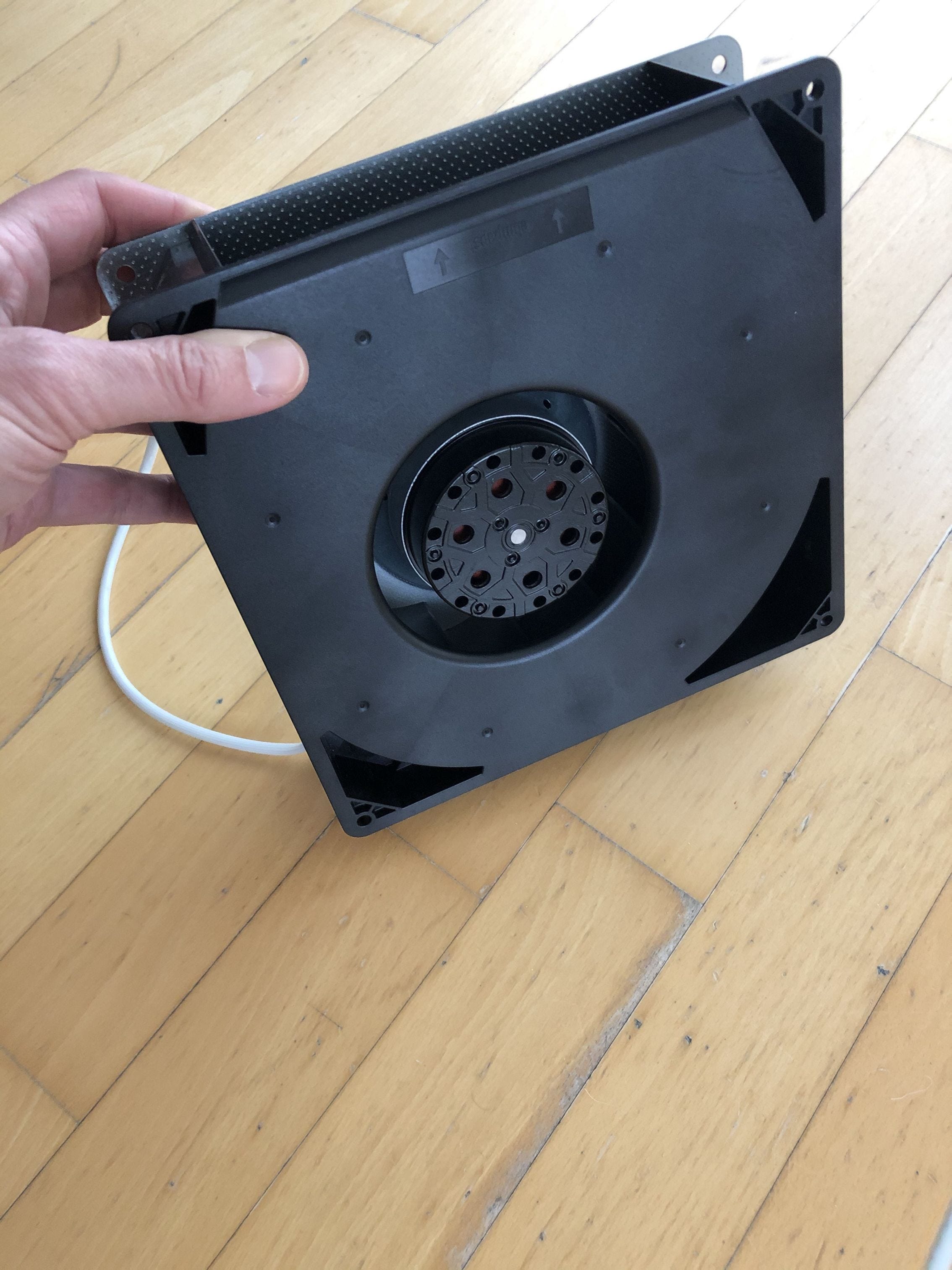
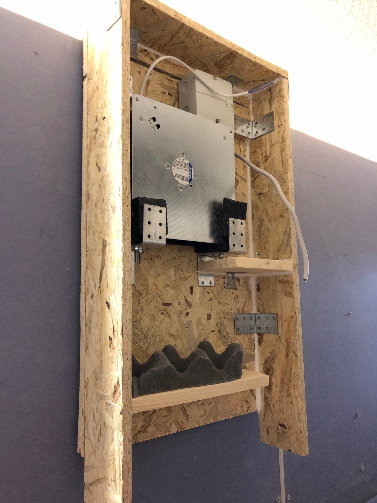
The air is sucked out by a radial fan at the top left (outside). The ebmpapst RG 160–28/56S fan model runs at max. 2750 rpm and exchanges 202m³ of air per hour. If I ignore the resistance of the labyrinth, the indoor air (approx. 12m³) would be renewed in less than 4 minutes.
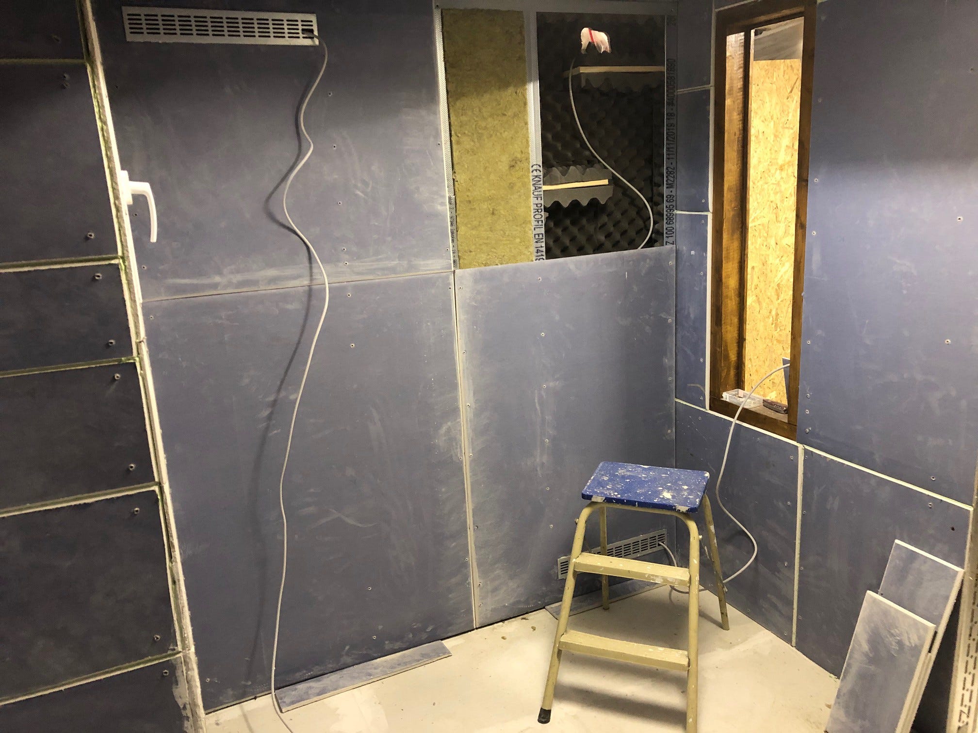
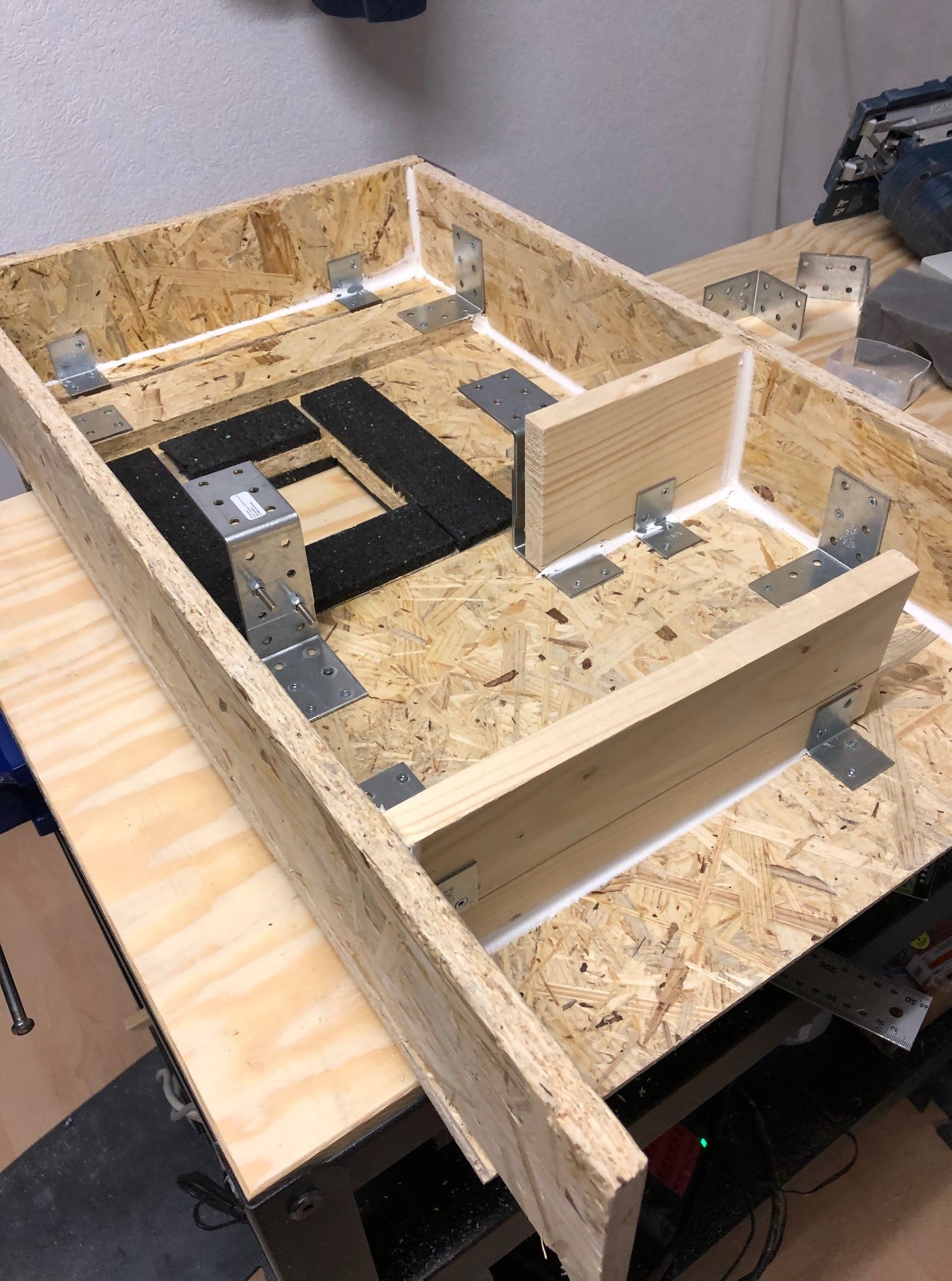
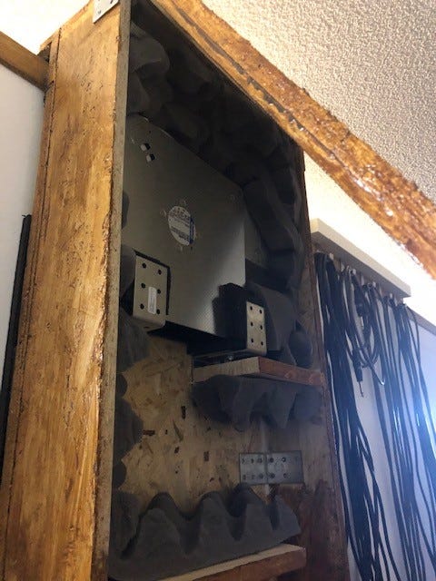
The actual construction differs somewhat from the model. From the inside perspective, the air discharge will now be seen on the right and the supply on the left. In order to achieve a sufficiently large cross-section for the volume flow, I built a frame from two 75mm profiles in a row.
The wooden boards are attached to the gypsum fiber boards with metal brackets and clamped in the profiles. The interior cladding is a bit fiddly: the cutouts for the ventilation grilles have to be milled and sawn, and the dimpled foam for the gaps between the boards cut and stapled.
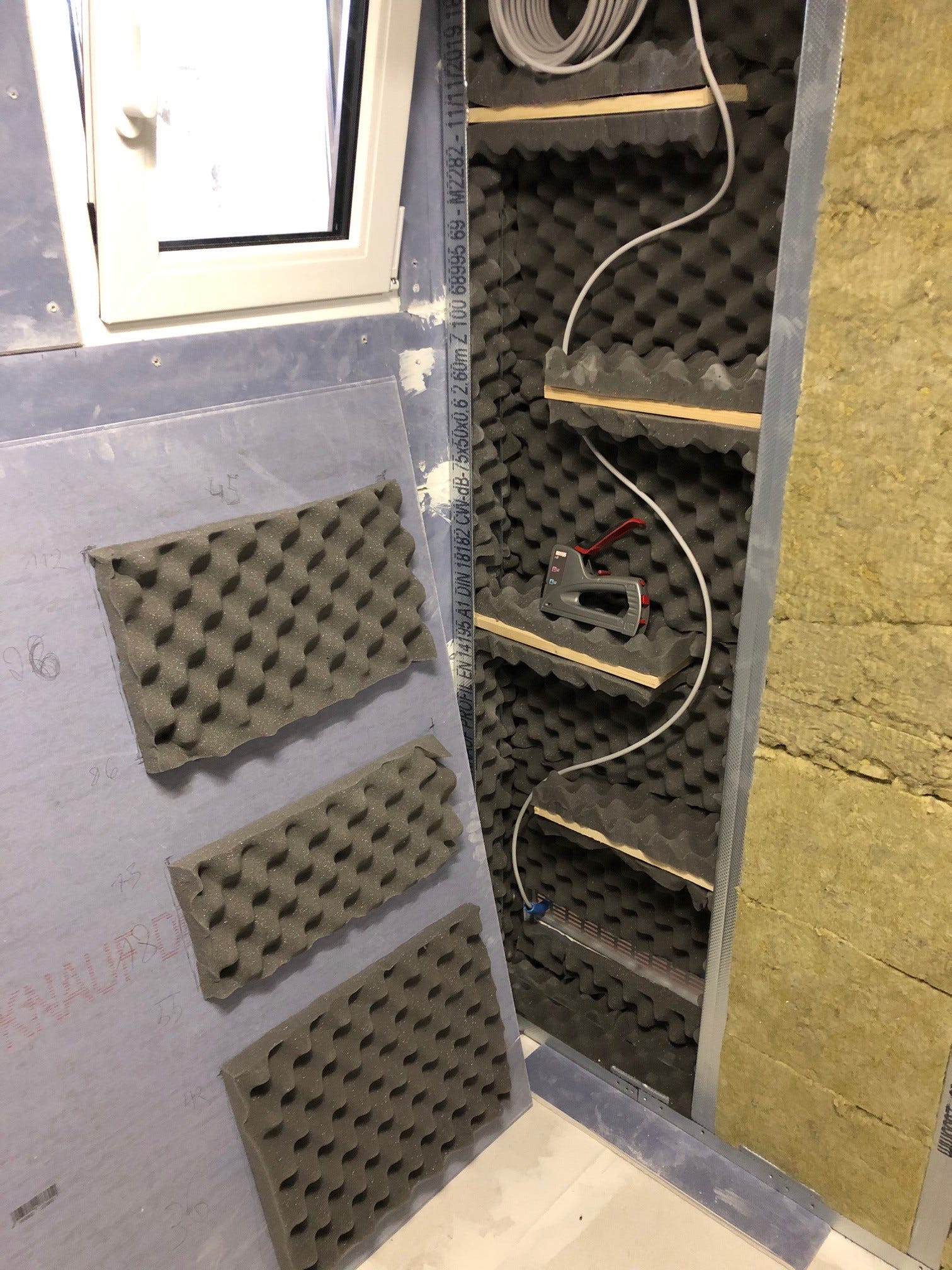
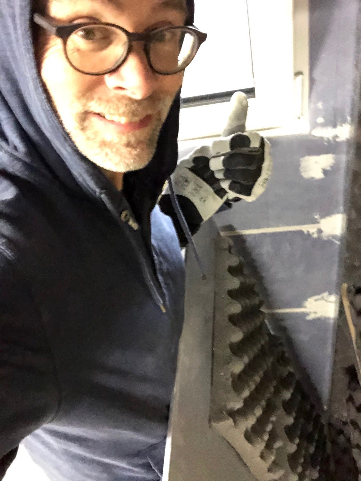
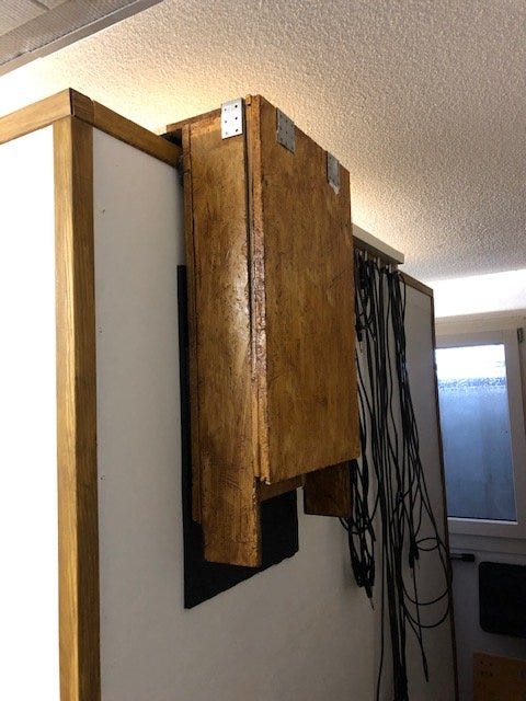
I led power cables from the outside through the ventilation grilles. For better maintenance options, I installed the fan on the outside of the cabin with a box containing a labyrinth. The fan and the cabin are mounted on foam rubber so that no vibrations are transmitted to the cabin.
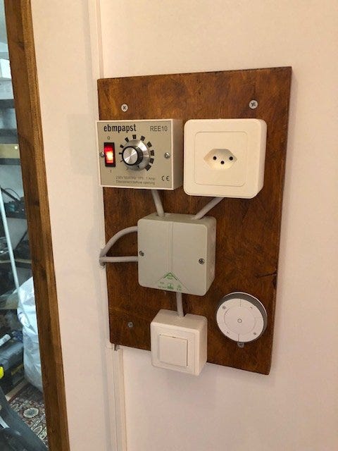
Last but not least, I gave the fan a speed controller. The speed controller from ebmpapst REE10 was not easy to get — I finally found it online in England. The finished fan housing got a cover in "rustic oak" — subtly blending with the rest of the vintage flair of the cabin.
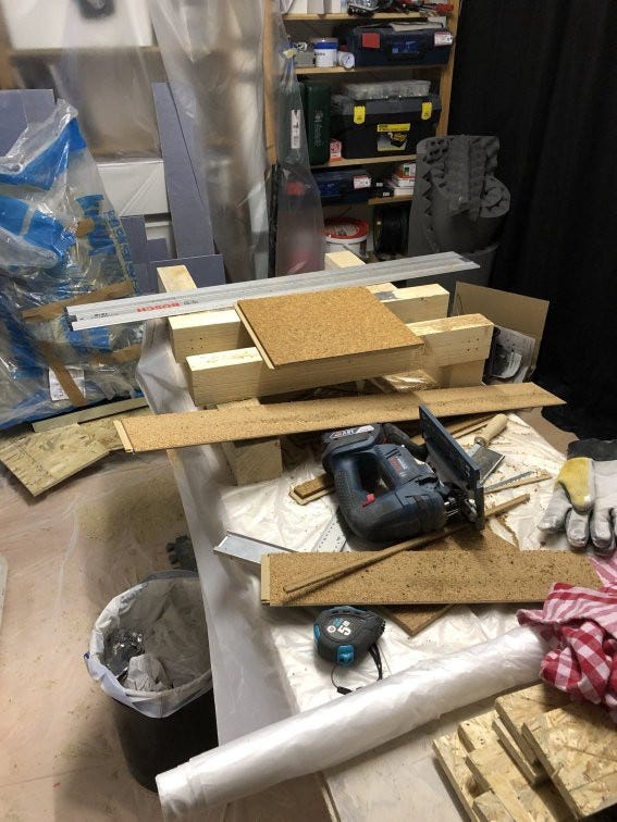
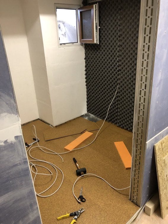
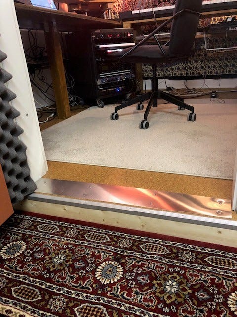
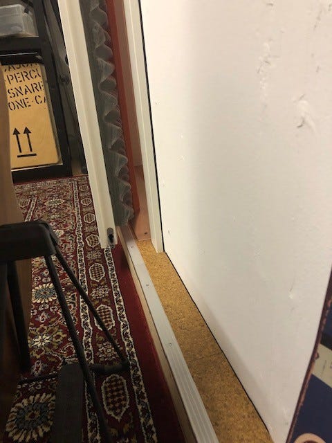
Cork flooring.
In order to have it a bit more comfortable under my feet, I opted for a covering made of hard-wearing cork tiles. After laying a steam foil, I layered the tiles for 24 hours for acclimatization.
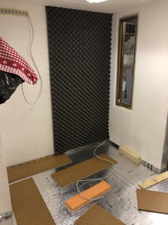
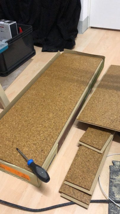
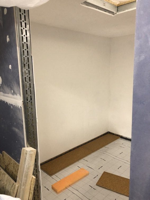
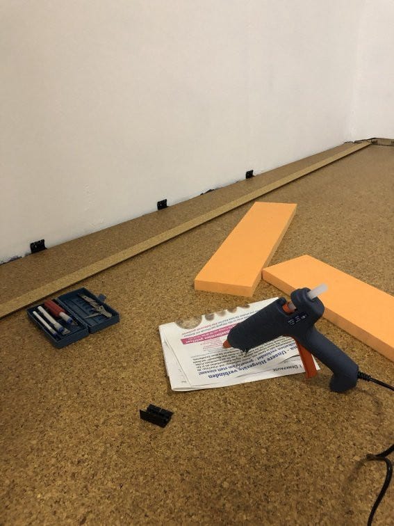
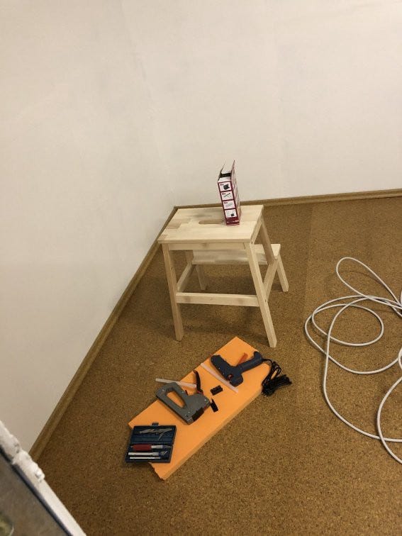
Cutting to size with a fine wood saw blade is easy — after a few hours all the tiles were laid. I used cork baseboards as a finish. Since I didn't want to drill any holes in the plasterboard, I attached the clips with hot glue. In the end, I left out the majority of the clips and stuck the strips directly to the walls.
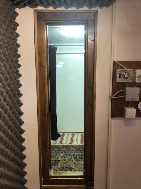
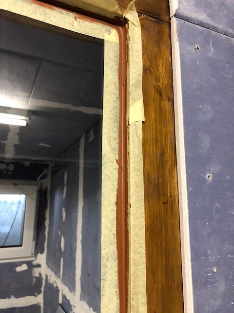
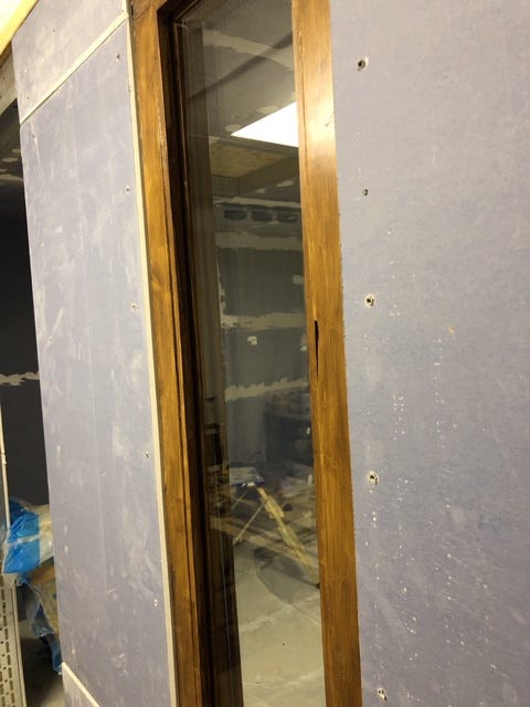
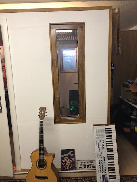
Custom window.
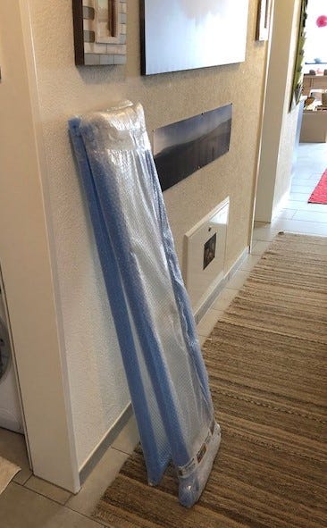
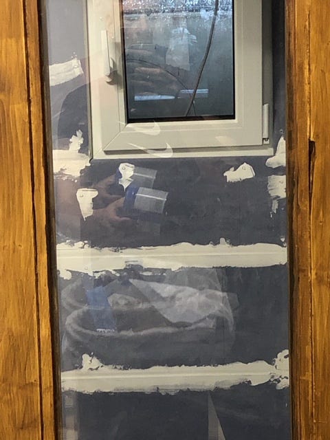
Although I don't need another window, I created a small challenge to satisfy my need for luxury. It should be self-made with optimized acoustic properties: double glazing with an 8mm and a 12mm slanted pane.
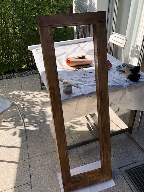
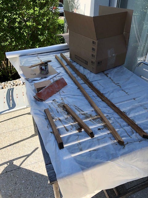
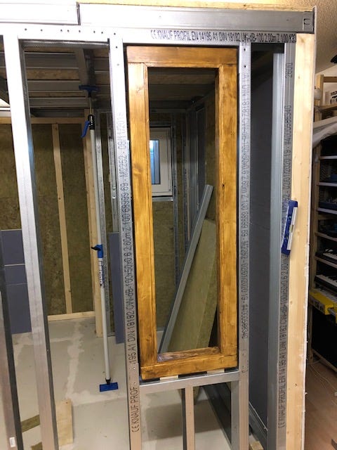
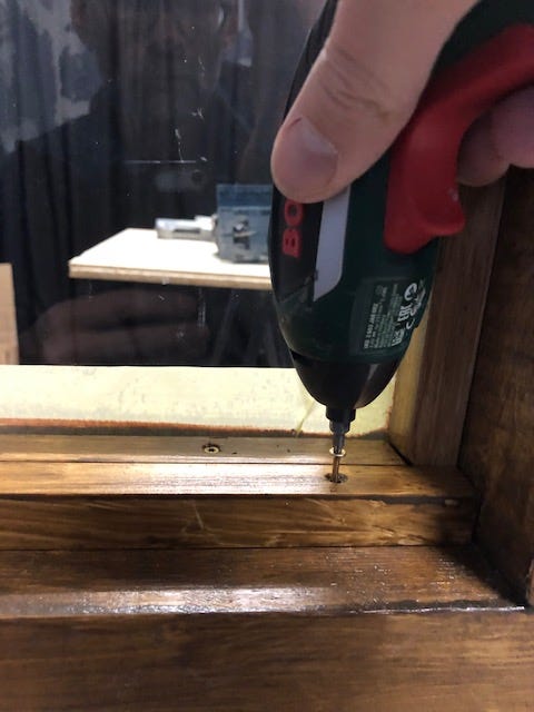
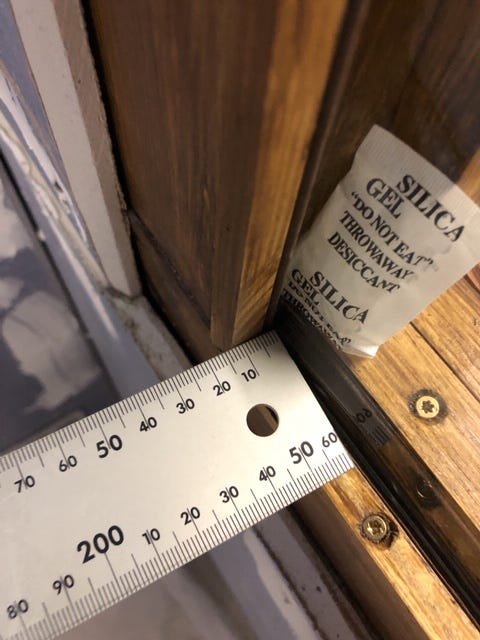
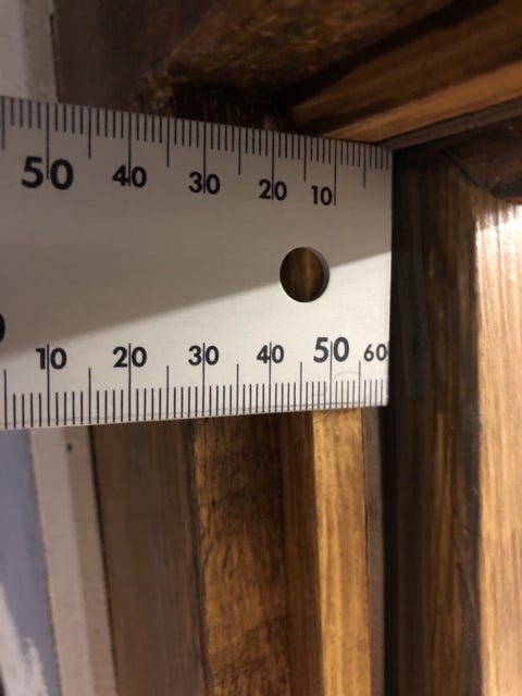
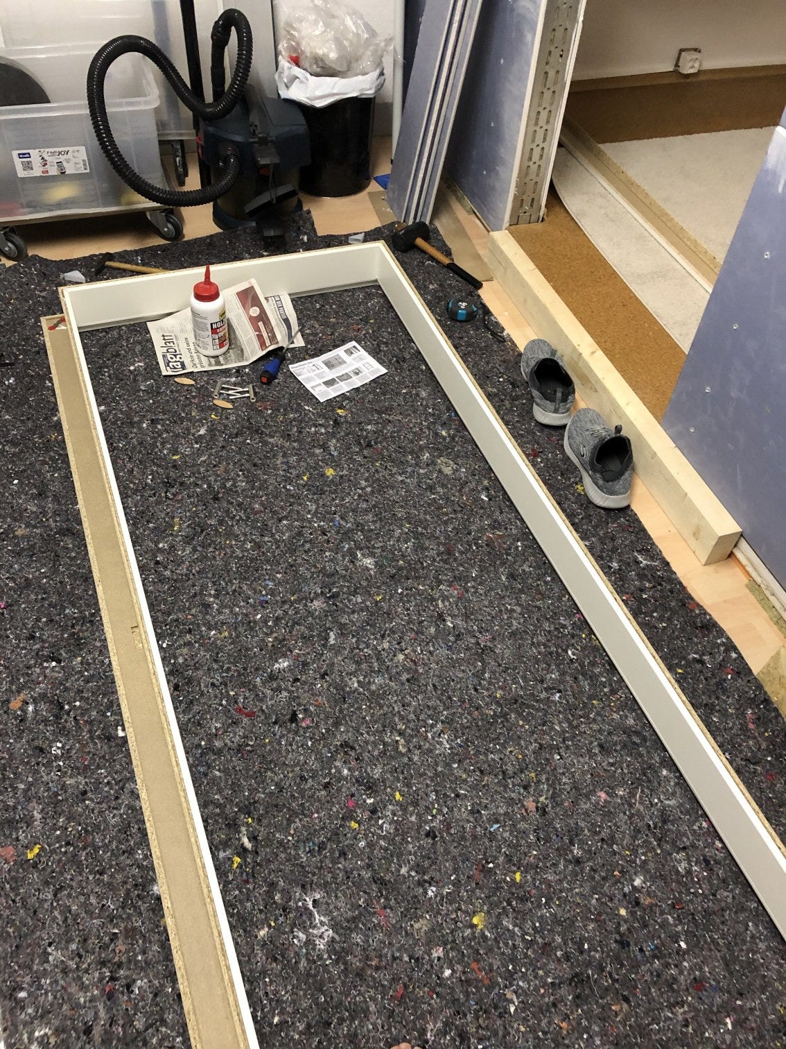
The frame construction consists of screwed 80×80mm square timber, supported by a UA profile in the metal frame. I sawed the frame and bars angled to hold the panes in place and painted them with wood varnish.
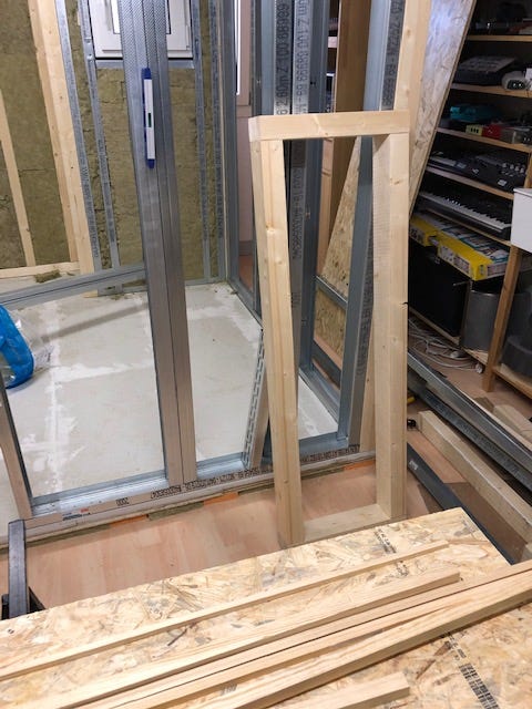
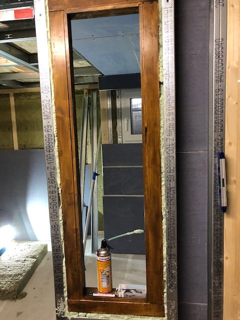
The wooden frame is screwed to the CW profiles and sealed with 2K construction foam. The first thinner 8mm pane is inserted and fixed with the profile strips, with self-adhesive rubber P-profile seals and brown acrylic. Brown, because a white seal would be reflected from the inside of the panes.
At the bottom it's 15mm from the frame to the window and at the top just under 40mm — on a length of 1200mm, a difference of 25mm. If Pythagoras wasn't completely wrong, the angle is slightly less than 2°. With this construction, less resonance should form and flutter echoes should be avoided.
The weakest element.
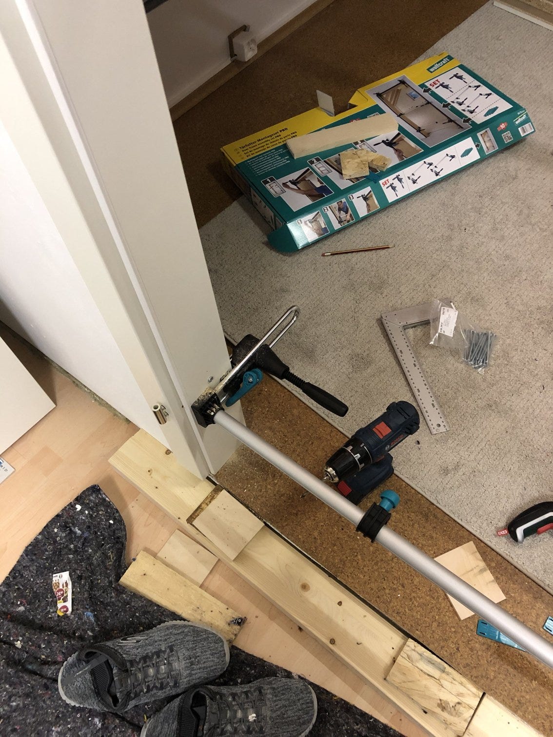
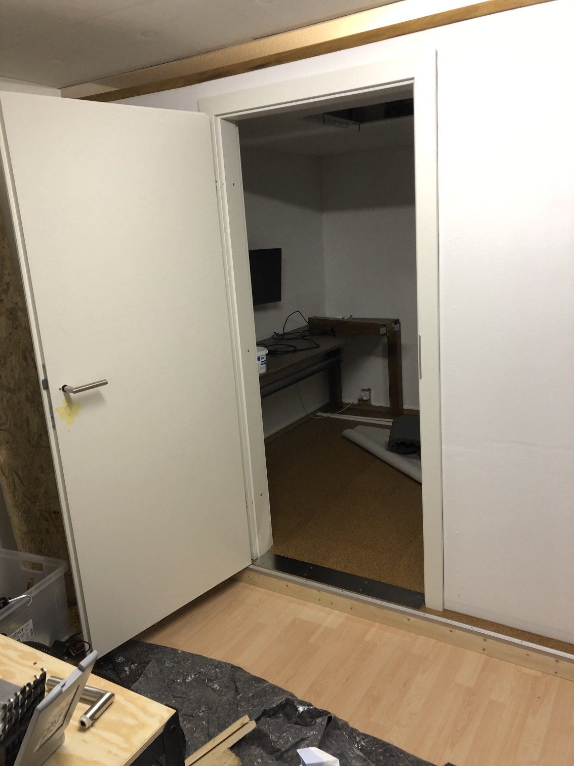
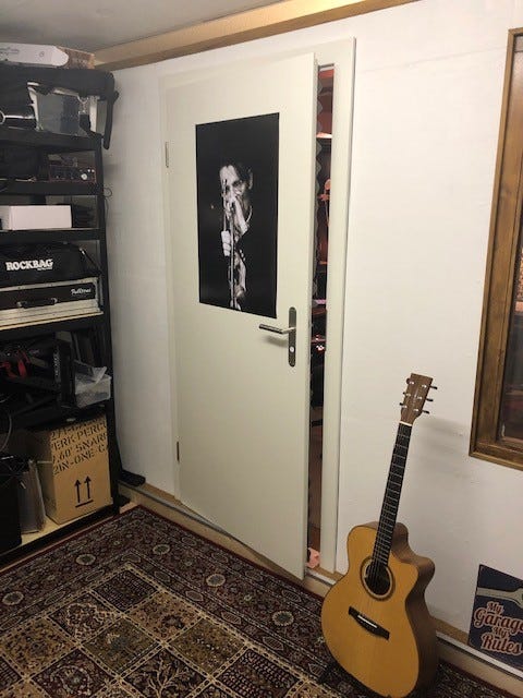
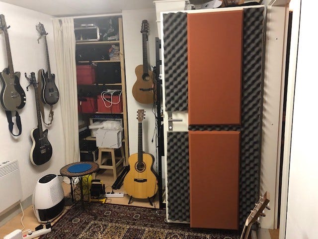
Doors — the weakest elements in terms of sound insulation — require special attention. 80 kg heavy and equipped with a retractable smoke protection, I had respect for the installation. I ordered the door (soundproof door set white RAL 9010 CPL with surrounding frame, 37 dB Rw, soundproofing class 2) in a set with the frame. A damping level of 37 dB Rw seemed sufficient for my purpose.
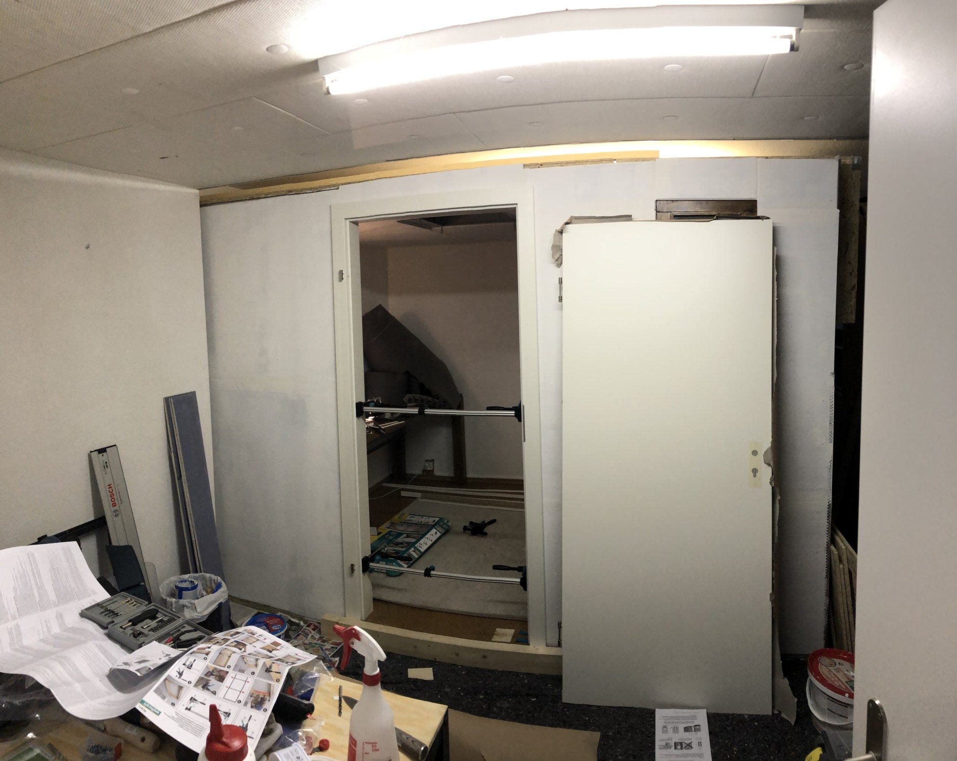
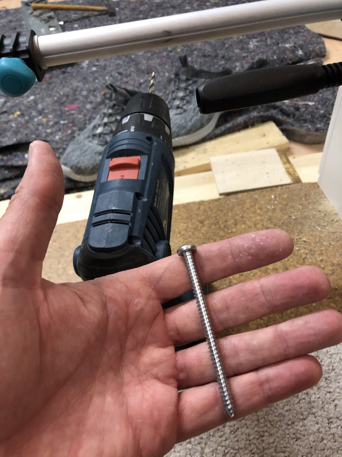
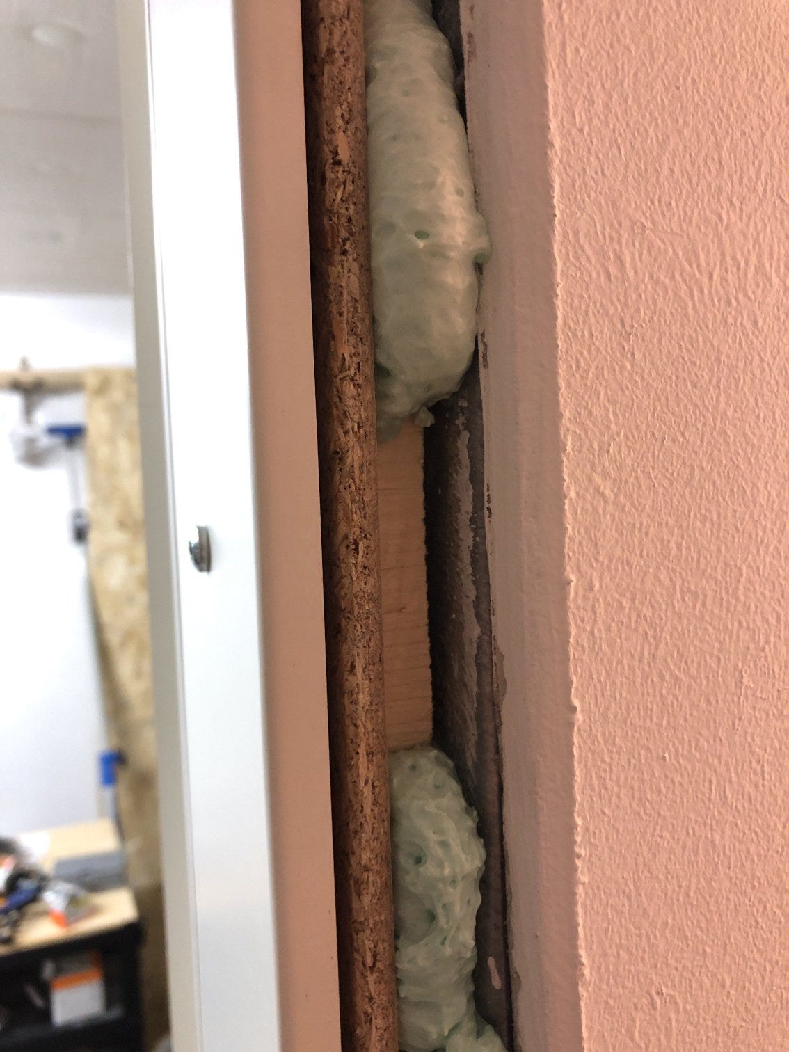
How do you fix a door frame that has to carry extra weight into a free-standing drywall made of metal profiles? Extra strong self-tapping screws are drilled through the frame backed with wooden panels and screwed into the metal profiles. Afterwards, everything stays in place with foam.
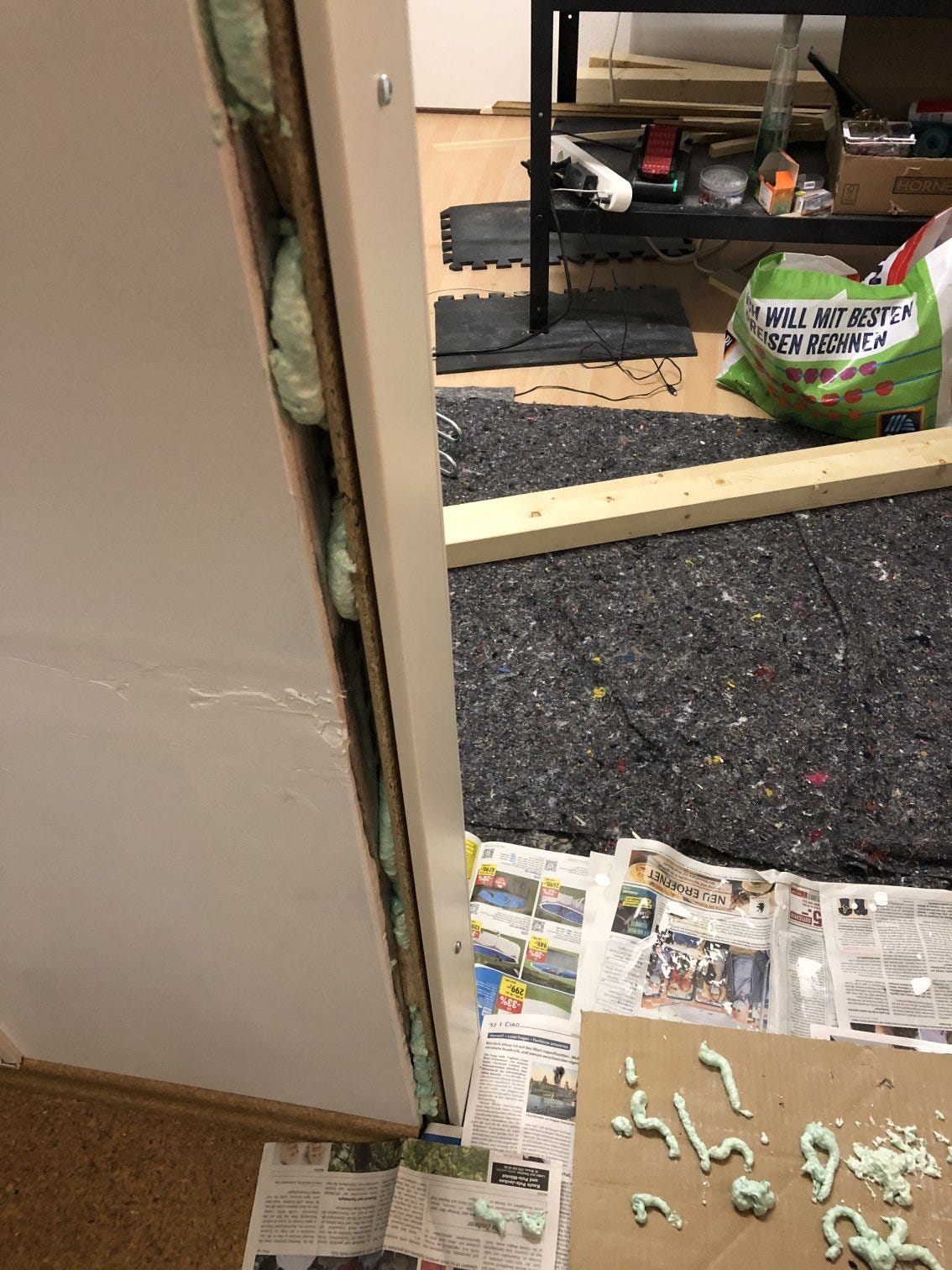
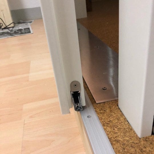
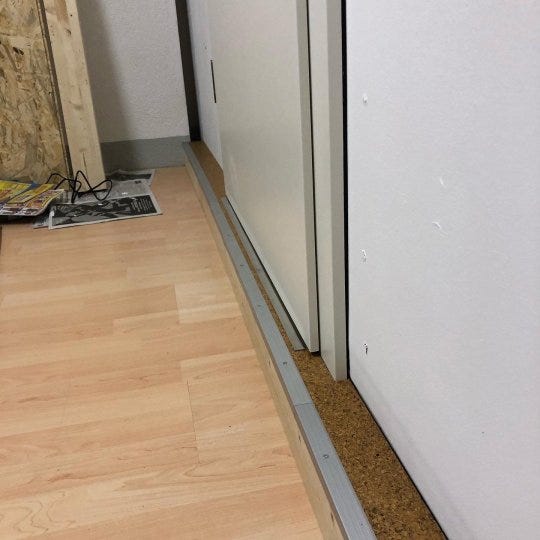
During assembly, I noticed that the door is sitting in the frame but protruding slightly — the retractable smoke protection hangs ineffectively in the air. A (not planned) door threshold, extended across the entire width of the cabin, offers enough resistance for the smoke protection and seals well. Remnants of the cork tiles and aluminium profiles for stair nosings make the construction reasonably pretty.
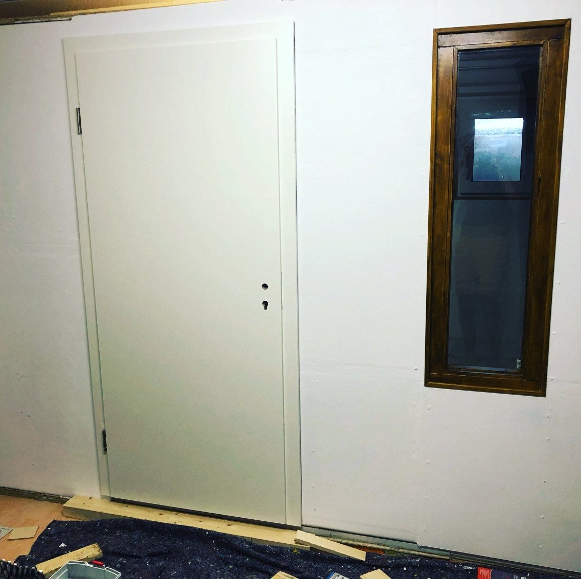
When closing, you notice a slight counter pressure — the room air is slightly compressed, which indicates good air and therefore sound insulation. Great!
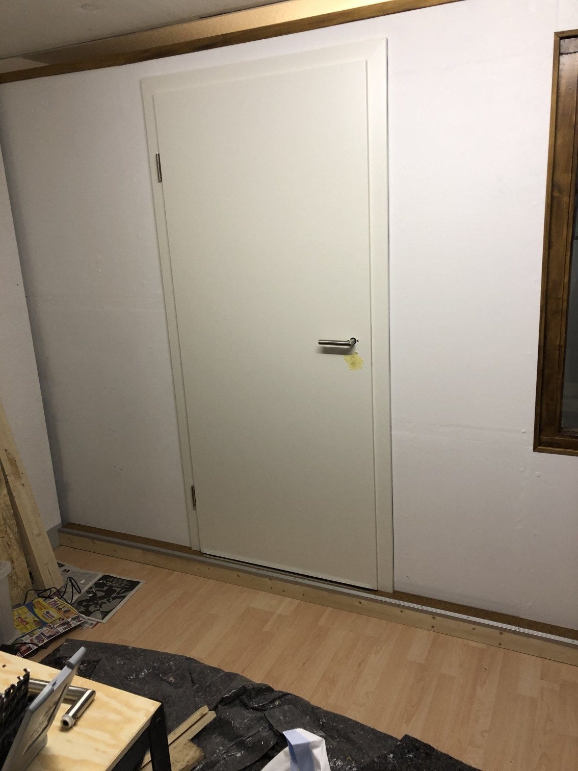
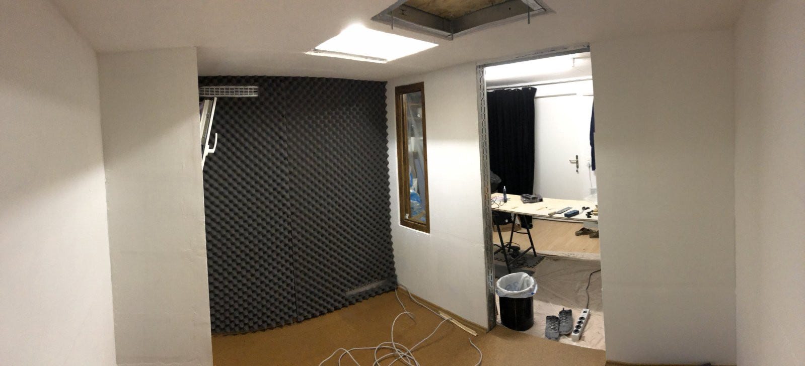
Done.
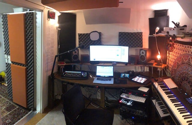
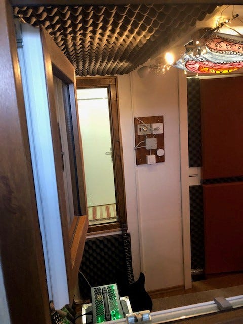
… some impressions of the completed cabin from outside …
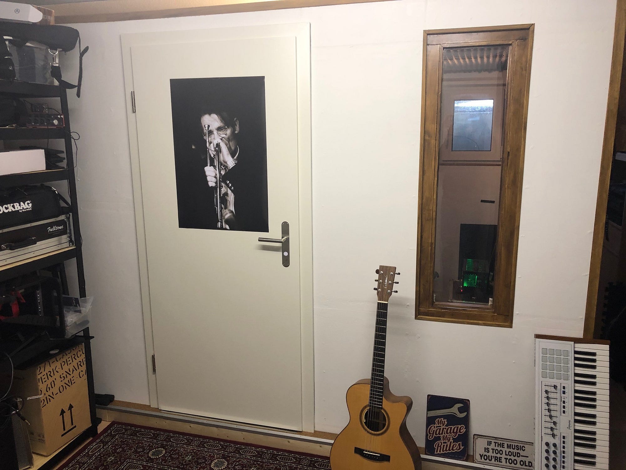
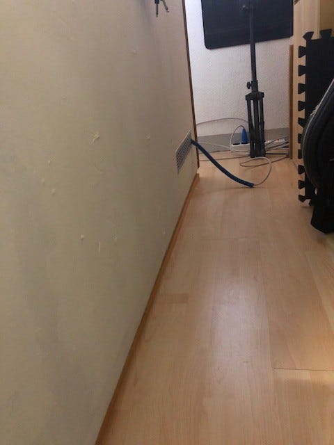
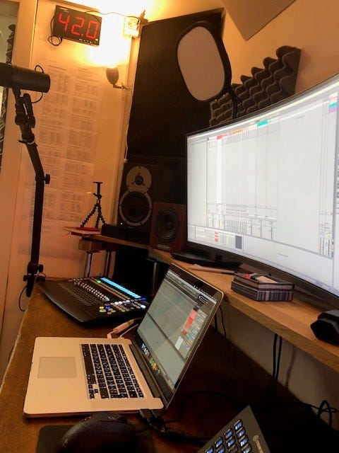
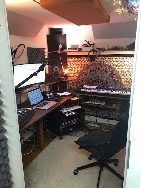
… and inside.
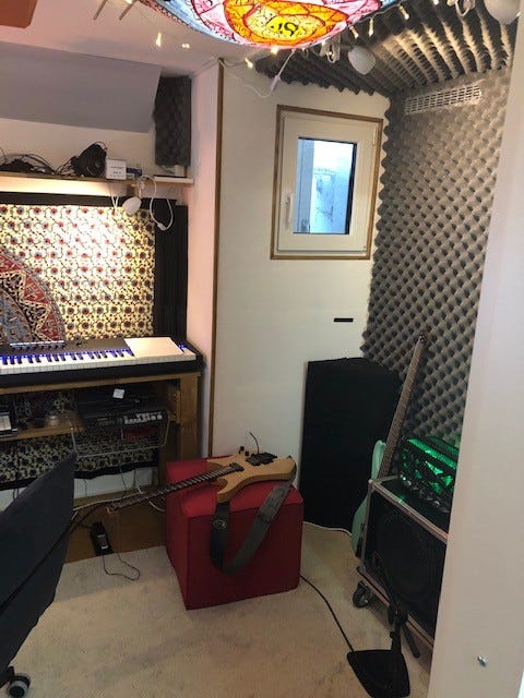
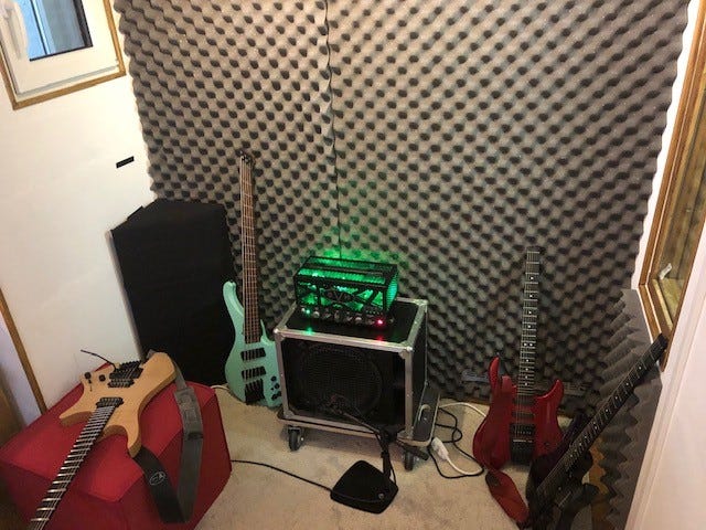
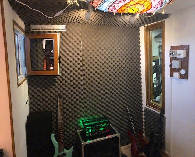
In case you want to know how to construct simple bass traps (as shown in the corners above), I recommend the DIY Basstraps article.